
Manual

11
AT86RF230
5131A-ZIGB-06/14/06
4. Basic Operating Modes
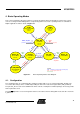
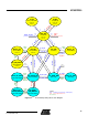
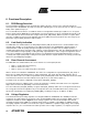
This section summarizes all features that are needed to provide the basic functionality of a transceiver system,
such as receiving and transmitting frames, and powering down. These basic operating modes are sufficient for
ZigBee applications and are shown in Figure 4-1.
2
T
R
X
_
O
F
F
S
L
P
_
T
R
=
1
Legend:
Blue: SPI Write to Register TRX_STATE (0x02)
Red: Control signals via IC Pin
Green: Event
S
L
P
_
T
R
=
0
P
L
L
_
O
N
RX_ON
PLL_ON
TRX_OFF
(Clock Mode)
XOSC=ON
Pull=OFF
R
X
_
O
N
P_ON
(Power-on after VDD)
XOSC=ON
Pull=ON
SLEEP
(Sleep Mode)
XOSC=OFF
Pull=OFF
(all modes except P_ON)
FORCE_TRX_OFF
(all modes except SLEEP)
Frame
Start
Frame
End
Frame
End
BUSY_TX
(Transmit Mode)
PLL_ON
(PLL Mode)
RX_ON
(Rx Listen Mode)
BUSY_RX
(Receive Mode)
CLKM=ON
TX_START
SLP_TR=1
T
R
X
_
O
F
F
T
R
X
_
O
F
F
1
3
4
57
6
8
9
11
10
RX_ON_NOCLK
(Rx Listen Mode)
CLKM=OFF
S
L
P
_
T
R
=
1
S
L
P
_
T
R
=
0
Frame
Start
CLKM=ON
RST=0
12
13
Figure 4-1. Basic Operating Modes State Diagram
4.1. Configuration
The operating modes are controlled by two signal pins and the SPI access to register 0x02 (TRX_STATE). The
successful state change can be confirmed by reading the transceiver state from register 0x01 (TRX_STATUS).
The pin SLP_TR is used to enter SLEEP mode where current consumption is minimal (leakage current only) and to
wake-up the transceiver.
The pin
RST
provides a reset of all registers and forces the transceiver into TRX_OFF mode, if the IC is not in the
P_ON mode.