
Manual


42
AT84AD004
5390A–BDC–06/04
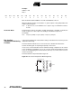
Example:
Address = 110
Data =
One should then obtain 01010101 on Port B and 10101010 on Port A.
When the dynamic mode is chosen (Data1 = 1) port B outputs a rising ramp while Port A
outputs a decreasing one.
Note: In dynamic mode, use the DRDA function to align the edges of CLKO with the middle of
the data.
Decimation Mode The decimation mode is provided to enable rapid testing of the ADC. In decimation
mode, one data out of 16 is output, thus leading to a maximum output rate of
31.25 Msps.
Note: Frequency (CLKO) = frequency (Data) = Frequency (CLKI)/16.
Die Junction
Temperature Monitoring
Function
A die junction temperature measurement setting is included on the board for junction
temperature monitoring.
The measurement method forces a 1 mA current into a diode-mounted transistor.
Caution should be given to respecting the polarity of the current.
In any case, one should make sure the maximum voltage compliance of the current
source is limited to a maximum of 1V or use a resistor serial-mounted with the current
source to avoid damaging the transistor device (this may occur if the current source is
reverse-connected).
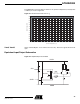
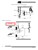
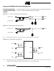
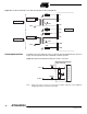
The measurement setup is illustrated in Figure 42.
Figure 42. Die Junction Temperature Monitoring Setup
D15 D14 D13 D12 D11 D10 D9 D8 D7 D6 D5 D4 D3 D2 D1 D0
XXXXXX0101010101
1 mA
GNDD
(Pin 36)
VDiode (Pin 35)
Protection
Diodes