
Owner manual

52
AT84AD001B
2153C–BDC–04/04
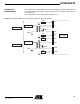
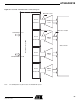
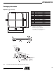
Figure 57. Termination Method for the ADC Analog Inputs in AC Coupling Mode
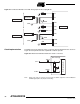
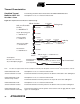
Clock Implementation The ADC features two different clocks (I or Q) that must be implemented as shown in
Figure 58. Each path must be AC coupled with a 100 nF capacitor.
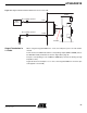
Figure 58. Differential Termination Method for Clock I or Clock Q
Note: When only clock I is used, it is not necessary to add the capacitors on the CLKQ and
CLKQN signal paths; they may be left floating.
Channel I
Channel Q
50Ω Source
VinI
VinIB
VinQ
VinQB
VinI
VinIB
VinQ
VinQB
Dual ADC
50Ω
50Ω
50Ω
50Ω
GND
GND
50Ω Source
GND
GND
ADC Package
VCCD/2
50Ω
50Ω
100 nF
100 nF
Differential Buffer
CLK
CLKB