
Manual


AT75C310
85
TC User Interface
TC Base Address: 0xFF014000
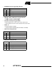
TC_BCR (Block Control Register) and TC_BMR (Block Mode Register) control the TC block. TC channels are controlled by
the registers listed in Table 19. The offset of each of the channel registers in Table 19 is in relation to the offset of the cor-
responding channel as stated in Table 18.
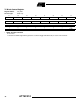
Note: 1. Read only if WAVE = 0
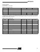
Table 18. TC Global Memory Map
Offset Channel/Register Name Access Reset State
0x00 TC Channel 0 See Table 19
0x40 TC Channel 1 See Table 19
0x80 TC Channel 2 See Table 19
0xC0 TC Block Control Register TC_BCR Write-only –
0xC4 TC Block Mode Register TC_BMR Read/write 0
Table 19. TC Channel Memory Map
Offset Register Description Register Name Access Reset State
0x00 Channel Control Register TC_CCR Write-only –
0x04 Channel Mode Register TC_CMR Read/write 0
0x08 Reserved –
0x0C Reserved –
0x10 Counter Value Register TC_CVR Read/write 0
0x14 Register A TC_RA Read/write
(1)
0
0x18 Register B TC_RB Read/write
(1)
0
0x1C Register C TC_RC Read/write 0
0x20 Status Register TC_SR Read-only –
0x24 Interrupt Enable Register TC_IER Write-only –
0x28 Interrupt Disable Register TC_IDR Write-only –
0x2C Interrupt Mask Register TC_IMR Read-only 0