
Manual

AT75C310
68
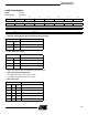
USART Channel Status Register
Name: US_CSR
Access Type: Read-only
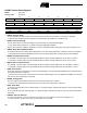
• RXRDY: Receiver Ready
0 = No complete character has been received since the last read of the US_RHR or the receiver is disabled.
1 = At least one complete character has been received and the US_RHR has not yet been read.
• TXRDY: Transmitter Ready
0 = US_THR contains a character waiting to be transferred to the Transmit Shift Register.
1 = US_THR is empty and there is no break request pending TSR availability.
Equal to zero when the USART is disabled or at reset. Transmitter Enable command (in US_CR) sets this bit to one.
• RXBRK: Break Received/End of Break
0 = No Break Received nor End of Break detected since the last “Reset Status Bits” command in the Control Register.
1 = Break Received or End of Break detected since the last “Reset Status Bits” command in the Control Register.
• ENDRX: End of Receive Transfer
0 = The End of Transfer signal from the Peripheral Data Controller channel dedicated to the receiver is inactive.
1 = The End of Transfer signal from the Peripheral Data Controller channel dedicated to the receiver is active.
• ENDTX: End of Transmit Transfer
0 = The End of Transfer signal from the Peripheral Data Controller channel dedicated to the transmitter is inactive.
1 = The End of Transfer signal from the Peripheral Data Controller channel dedicated to the transmitter is active.
• OVRE: Overrun Error
0 = No byte has been transferred from the Receive Shift Register to the US_RHR when RxRDY was asserted since the
last “Reset Status Bits” command.
1 = At least one byte has been transferred from the Receive Shift Register to the US_RHR when RxRDY was asserted
since the last “Reset Status Bits” command.
• FRAME: Framing Error
0 = No stop bit has been detected low since the last “Reset Status Bits” command.
1 = At least one stop bit has been detected low since the last “Reset Status Bits” command.
• PARE: Parity Error
1 = At least one parity bit has been detected false (or a parity bit high in multi-drop mode) since the last “Reset Status
Bits” command.
0 = No parity bit has been detected false (or a parity bit high in multi-drop mode) since the last “Reset Status Bits”
command.
• TIMEOUT: Receiver Time-out
0 = There has not been a time-out since the last “Start Time-out” command or the Time-out Register is 0.
1 = There has been a time-out since the last “Start Time-out” command.
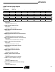
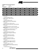
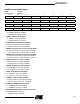
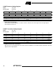
31 30 29 28 27 26 25 24
––––––––
23 22 21 20 19 18 17 16
––––––––
15 14 13 12 11 10 9 8
–––––DMSI TXEMPTY TIMEOUT
76543210
PARE FRAME OVRE ENDTX ENDRX RXBRK TXRDY RXRDY