
Manual

AT75C310
64
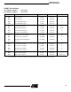
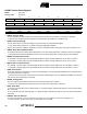
• NBSTOP: Number of Stop Bits
The interpretation of the number of stop bits depends on SYNC.
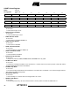
• CHMODE: Channel Mode
• MODE9: 9-bit Character Length
0 = CHRL defines character length.
1 = 9-bit character length.
• CKLO: Clock Output Select
0 = The USART does not drive the SCK pin.
1 = The USART drives the SCK pin if USCLKS[1] is 0.
NBSTOP
Asynchronous
(SYNC = 0)
Synchronous
(SYNC = 1)
0 0 1 stop bit 1 stop bit
0 1 1.5 stop bits Reserved
1 0 2 stop bits 2 stop bits
1 1 Reserved Reserved
CHMODE Mode Description
0 0 Normal Mode
The USART Channel operates as an Rx/Tx USART.
0 1 Automatic Echo
Receiver Data Input is connected to TXD pin.
1 0 Local Loopback
Transmitter Output Signal is connected to Receiver Input Signal.
1 1 Remote Loopback
RXD pin is internally connected to TXD pin.