
Manual

AT75C310
26
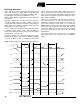
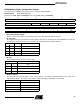
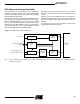
DRAM Common Configuration Register (DMC_CR)
The Common Configuration Register defines parameters which are common to the two DRAM regions.
Register Name: DMC_CR
Reset Value is 0x00000000
• DBW: Data Bus Width
When high, the DRAM data bus is 32 bits wide. When low, the DRAM data bus is only 16 bits wide. The DMC splits 32-
bit transfers into two 16-bit transfers which are transparent to the ASB.
• BBR: Break Burst for Refresh
When this flag is high, the controller breaks long burst accesses every 32 CAS cycles if a refresh cycle is pending in
order to allow the refresh cycle to be performed. This prevents excessively long bursts from delaying refresh cycles.
• ROR: RAS-only Refresh
When high, the CAS signal is held inactive (high) during normal DRAM accesses, thereby generating a RAS-only
Refresh cycle. This feature allows software to generate the row address and initiate the refresh cycle. When low, mem-
ory operations behave as normal and CAS is not inhibited.
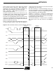
DRAM Interface
31 30 29 28 27 26 25 24
––––––––
23 22 21 20 19 18 17 16
––––––––
15 14 13 12 11 10 9 8
––––––––
76543210
–––––ROR BBR DBW
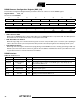
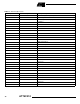
Table 10. DRAM Interface
FPDRAM Description Type Notes
NRAS[1:0]
Row Address Strobe O
One strobe per DRAM region. Common to four bytes in each region
NCAS[3:0]
Column Address
Strobe
O
One strobe per byte. Common to both DRAM regions. Only NCAS[1:0] used
when Data Bus Width is 16
NWE
Write Enable O
Common to both regions
NOE
Output Enable O
Common to both regions
A[14:0]
Address Bus O
Multiplexed row and column addresses
D[31:0]
Data Bus I/O
D[15:0] used when Data Bus Width is 16