
Manual

AT75C310
25
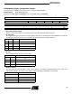
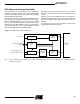
DRAM Memory Region Configuration Register
For each of the two DRAM memory regions there is a memory-mapped register.
Register Name: DMC_MR0..DMC_MR1
Reset value of DMC_MR0 is 0x40000000; reset value of DMC_MR1 is 0x50000000
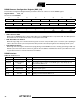
• EMR: Enable Memory Region
When low, the memory region is not enabled; any access to this region will generate an abort.
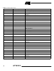
• PS: Page Size
This field should be set to the number of column address lines that are required by the external DRAM. It also indicates
the number of columns per page. The controller breaks sequential bursts on page boundaries.
• SZ: Size
This field indicates the size of the memory region.
• BA: Base Address
This field indicates the base address of the memory region. It should be programmed with the top 11 bits of the
required base address. The number of bits used for address decoding is dependent on the SZ field.
31 30 29 28 27 26 25 24
BA
23 22 21 20 19 18 17 16
BA –––––
15 14 13 12 11 10 9 8
––––––––
76543210
––– SZ PS EMR
PS Columns No. Column Address LInes
00
256 8
01
512 9
10
1024 10
1 1
2048 11
SZ Size of Memory Region
00 2 MB
01 4 MB
10 8 MB
1 1 16 MB
SZ BA Bits Used
2 MB BA[31:21]
4 MB BA[31:22]
8 MB BA[31:23]
16 MB BA[31:24]