
Manual

AT75C310
12
AT75C310 Mode Controller
The mode controller is a memory-mapped peripheral which sits on the APB. It is used to configure the mode in which the
AT75C310 operates.
Mode Register
Register Name: SIAP_MD
• RM: Remap
When reset is released, this flag is set to the value of NDSRA/BOOTN. When RM is active low, the Boot ROM is
mapped to 0x00000000. Subsequently, this flag can be set high by software so that the ROM mapping is disabled and
another memory controller region (e.g., Flash) is mapped to location 0x00000000.
• RA: OAKA Reset
This flag resets to active low so that the Oak A is held in reset. The Oak A is released from reset by asserting this flag
high and then low three times. This generates the required reset sequence to the Oaks of 010101.
• RB: OAKB Reset
This flag resets to active low so that Oak B is held in reset. The Oak B is released from reset by asserting this flag high
and then low three times. This generates the required reset sequence to the Oaks of 010101.
• IA: Inhibit Oak A Clock
This flag resets to active low so that the Oak A clock is enabled. The Oak A clock is inhibited by asserting this flag high.
• IB: Inhibit Oak B Clock
This flag resets to active low so that the Oak B clock is enabled. The Oak B clock is inhibited by setting this flag high.
• CS: Synchronous Clock Mode
When high, the ARM, Oak A and Oak B run from the OakDSPCore clock, thus the ARM runs at 20 MHz and the
OakDSPCores at 40 MHz. When low, the ARM and OakDSPCores run from asynchronous clocks.
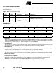
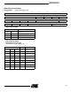
Table 5. Mode Controller Registers Map
Register
Address
Register
Name Description Access Reset Value
0x0 SIAP_MD Mode Register Read/write 0x00000001 if NDSRA/BOOTN is 1; else0x00000000
0x4 SIAP_ID ID Register Read 0x00010001 for 240-lead package;
0x00000001 for 160-lead package
0x8 SIAP_RST Reset Status
Register
Read/write 0x00000001 after hard reset
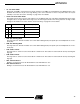
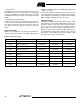
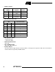
31 30 29 28 27 26 25 24
––––––––
23 22 21 20 19 18 17 16
––––––––
15 14 13 12 11 10 9 8
CRB CRA DBB DBA SW2 SW1 LPCS
76543210
– LP CS IB IA RB RA RM