
User Manual


AT73C500
9
Measurements and Calculations
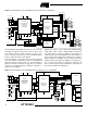
The first operation performed by AT73C500 is digital high-
pass filtering. The purpose of the filtering is to remove the
DC offset of both current and voltage samples.
From offset free samples, active power is calculated
phase-by-phase with simple multiplication and addition
operations.
First, the current samples are multiplied by voltage sam-
ples. The multiplication results are summed over one line
period and finally the sum value is divided by 64. This dis-
crete time operation gives the average power of one 50 Hz
period and the result corresponds to the following continu-
ous time formula:
where
T = 1/50 Hz,
n = 1, 2, 3,..., 20 (basic 50 Hz frequency and the har-
monics),
A
n
= frequency response of calculations.
This method of calculation does take into account the effect
of harmonics.
The total power is calculated by summing the power of
each line phase. Reactive power calculation is based on a
similar procedure. Before multiplying the current and volt-
age samples AT73C500 performs a frequency independent
90 degree phase shift of the voltage signal. This is realized
with a digital Hilbert transformation filter. The bandwidth of
reactive power measurement is limited to 360 Hz.
Based on the active and reactive results apparent power
and power factors are determined. RMS phase voltages
are calculated by squaring and summing the voltage sam-
ples and finally taking a square root of the results. Current
is determined by dividing apparent power result by corre-
sponding phase voltage.
Frequency measurement is based on a comparison of the
line frequency and AT73C500 sampling clock frequency.
The measurement range is from 20 Hz to 350 Hz.
All measurements and calculations, except frequency mea-
surement, are made over 10 line cycle periods. The results
are updated and transferred to processor bus once in 200
ms.
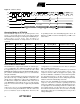
Measurement Registers
For the measurement parameters 25 registers are allo-
cated:
The size of the registers is either 16-bit or 32-bit. IEC spec-
ifications apply to the calculations of active and reactive
power and energy (REG 0-5 and REG 12-15). Other results
are intended mainly for demand recording and for various
diagnostic and display functions. The accuracy of those are
limited due to the finite resolution.
P
1
T
---
A
N
U
N
sin n wt×{}A
N
I
N
sin n wt ∅+×
N
{}dt×××××[]
0
T
∫
×
n0=
N
∑
=
1
2
---
A
n
A
n
U
n
I
n
cos ∅
n
()×××××
n0=
N
∑
=
Register Meaning
REG0 Phase 1, active power, P1(10T), 32-bit register;
REG1 Phase 2, active power, P2(10T), 32-bit register;
REG2 Phase 3, active power, P3(10T), 32-bit register;
REG3 Phase 1, reactive power, Q1(10T), 32-bit register;
REG4 Phase 2, reactive power, Q2(10T), 32-bit register;
REG5 Phase 3, reactive power, Q3(10T), 32-bit register;
REG6 Phase 1, apparent power, S1(10T), 16-bit register;
REG7 Phase 2, apparent power, S2(10T), 16-bit register;
REG8 Phase 3, apparent power, S3(10T), 16-bit register;
REG9 Phase 1, power factor, PF1, 16-bit register;
REG10 Phase 2, power factor, PF2, 16-bit register;
REG11 Phase 3, power factor, PF3, 16-bit register;
REG12
Active exported energy since the latest reset, +Wp,
32-bit counter;
REG13
Active imported energy since the latest reset, -Wp,
32-bit counter;
REG14
Reactive energy, inductive load, Wqind, 32-bit
counter;
REG15
Reactive energy, capacitive load, Wqcap, 32-bit
counter;
REG16
Number of 10T periods elapsed since the latest
reset, 32-bit counter;
REG17 Frequency, f, 16-bit register;
REG18 Reserved for further use, 16-bit register;
REG19 Phase 1, voltage U1, 16-bit register;
REG20 Phase 2, voltage U2, 16-bit register;
REG21 Phase 3, voltage U3, 16-bit register;
REG22 Phase 1, current I1, 16-bit register;
REG23 Phase 2, current I2, 16-bit register;
REG24 Phase 3, current I3, 16-bit register.