
User Manual


AT73C500
8
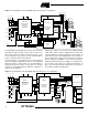
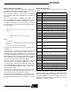
Figure 8. Serial bus timing
Operating Modes of AT73C500
The AT73C500 chipset has six operating modes. The
mode is selected by three mode control inputs which
AT73C500 reads through a bus during the initialization pro-
cedure after a reset state. The operation of
AT73C501/AT73C502 is independent of the mode
selected.
In operating mode 7, the default display pulse rate is 10
impulses per kWh, instead of 100 impulses per kWh, as in
other modes.
Normal Measurement Mode
AT73C500 devices support both stand-alone and micropro-
cessor configuration. The calibration coefficients can either
be supplied by a processor or stored in an 128 x 8-bit
EEPROM. The ROM is interfaced with AT73C500 via three
pin serial bus. AT73C500 and the processor communicate
through an 8-bit bus.
The only operational difference between stand-alone and
µP mode is the way of reading calibration coefficients. This
allows various combinations of these two configurations to
be utilized. For example, the calibration data can be stored
in an EEPROM even though the processor reads and dis-
plays the measurement results supplied by AT73C500
device.
In most cases, the use of external EEPROM gives flexibility
to the meter testing and calibration, and also makes the
processor interface easier to implement. Therefore, this
configuration is recommended even in meters equipped
with a separate microprocessor.
The same sequence of basic calculations is performed
both in poly-phase and single-phase meters. This
sequence consists of DC offset suppression, phase, gain
and offset calibration, calculations of measurement quanti-
ties and data transfer to µP bus and pulse outputs.
AT73C500 constantly monitors various tampering and fault
situations, which are indicated by status bits.
After a reset state, AT73C500 goes through an initialization
sequence. The device reads the operating mode and
fetches the calibration coefficients and adjustment factors
for output pulse rate and starting current level, either from a
non-volatile memory or from a microprocessor. After that
the normal measurement starts. The reset state is normally
activated by power-up reset following the recovery from a
voltage interruption.
CLK
CLKR
ACK
FSR
CS
DATA
CH1, B15
MSB
CH1, B14 CH1, B0
LSB
CH2, B15
MSB
CH2, B0
LSB
CH6, B1 CH6, B0
6 * 16 BITS
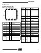
Mode Number Mode Bit 2 Mode Bit 1 Mode Bit 0 Operating Mode Calibration Data Storage
0000Not in use
1001Normal operationEEPROM
2010Multi-channel operationEEPROM
3011Normal operationMicro-processor
4100Multi-channel operationMicro-processor
5101Test mode None
6110Not in use
7111Normal operationEEPROM