
User Manual


AT73C500
25
The measurements are done according to IEC1036 specifi-
cation. The results are averaged over a period of 10s.
Before measurements, AT73C500 devices have been
operational for minimum 1h.
Effect of Crosstalk
The error caused by crosstalk from one current input to
other two current inputs when the meter is carrying a sin-
gle-phase load.
Influence Quantities
The additional error caused by different influence quanti-
ties.
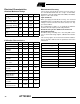
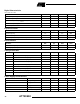
Table 9. Measurement Bandwidth
Parameter Min Typ Max Units
General, 50 Hz line
frequency
- high limit (-3dB) 750 Hz
- low limit (-3dB) 30 Hz
Reactive Power and
Energy, Voltage and
Current Measurement
- high limit 360 Hz
- low limit 40 Hz
Line Frequency
- high limit 350 Hz
- low limit 20 Hz
Table 10. Maximum Error
Current Voltage
Power
Factor Min Typ Max Units
0.05I
B
U
N
1.000 -0.4 +0.4 %
0.1I
B
...I
FS
U
N
1.000 -0.2 +0.2 %
0.1I
B
U
N
0.5
lagging
-0.4 +0.4
%
0.2I
B
...I
FS
U
N
0.5
lagging
-0.4 +0.4
%
0.1I
B
U
N
0.8
leading
-0.4 +0.4
%
0.2I
B
...I
FS
U
N
0.8
leading
-0.4 +0.4
%
0.2I
B
...I
FS
U
N
0.25
lagging
-1.0 +1.0
%
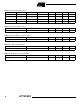
Table 11. Single-phase Load Error
Current Voltage
Power
Factor Min Typ Max Units
0.1I
B
...I
FS
U
N
1.000 -0.5 +0.5 %
0.1I
B
...I
FS
U
N
0.5
lagging
-0.5 +0.5 %
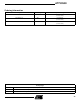
Table 12. Voltage Variation Error
Current Voltage
Power
Factor Min Typ Max Units
0.1I
B
0.9U
N
...
1.1U
N
1.000 -0.2 +0.2 %
0.1I
B
0.9U
N
...
1.1U
N
0.5
lagging
-0.2 +0.2 %