
User Manual

12
AT45DB642
1638F–DFLSH–09/02
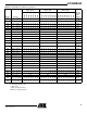
Note: In Tables 2 and 3, an SCK/CLK mode designation of “Any” denotes any one of the four modes of operation (Inactive Clock
Polarity Low, Inactive Clock Polarity High, SPI Mode 0, or SPI Mode 3).
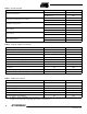
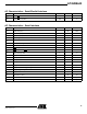
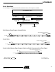
Table 1 . Read Commands
Command SCK/CLK Mode Opcode
Continuous Array Read
Inactive Clock Polarity Low or High 68H
SPI Mode 0 or 3 E8H
Burst Array Read with Synchronous Delay
Inactive Clock Polarity Low or High 69H
SPI Mode 0 or 3 E9H
Main Memory Page Read
Inactive Clock Polarity Low or High 52H
SPI Mode 0 or 3 D2H
Buffer 1 Read
Inactive Clock Polarity Low or High 54H
SPI Mode 0 or 3 D4H
Buffer 2 Read
Inactive Clock Polarity Low or High 56H
SPI Mode 0 or 3 D6H
Status Register Read
Inactive Clock Polarity Low or High 57H
SPI Mode 0 or 3 D7H
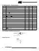
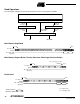
Table 2 . Program and Erase Commands
Command SCK/CLK Mode Opcode
Buffer 1 Write Any 84H
Buffer 2 Write Any 87H
Buffer 1 to Main Memory Page Program with Built-in Erase Any 83H
Buffer 2 to Main Memory Page Program with Built-in Erase Any 86H
Buffer 1 to Main Memory Page Program without Built-in Erase Any 88H
Buffer 2 to Main Memory Page Program without Built-in Erase Any 89H
Page Erase Any 81H
Block Erase Any 50H
Main Memory Page Program Through Buffer 1 Any 82H
Main Memory Page Program Through Buffer 2 Any 85H
Table 3 . Additional Commands
Command SCK/CLK Mode Opcode
Main Memory Page to Buffer 1 Transfer Any 53H
Main Memory Page to Buffer 2 Transfer Any 55H
Main Memory Page to Buffer 1 Compare Any 60H
Main Memory Page to Buffer 2 Compare Any 61H
Auto Page Rewrite Through Buffer 1 Any 58H
Auto Page Rewrite Through Buffer 2 Any 59H