
Instruction Manual

12
3597J–DFLASH–4/08
AT45DB321D
8.1 Software Sector Protection
8.1.1 Enable Sector Protection Command
Sectors specified for protection in the Sector Protection Register can be protected from program
and erase operations by issuing the Enable Sector Protection command. To enable the sector
protection using the software controlled method, the CS
pin must first be asserted as it would be
with any other command. Once the CS
pin has been asserted, the appropriate 4-byte command
sequence must be clocked in via the input pin (SI). After the last bit of the command sequence
has been clocked in, the CS
pin must be deasserted after which the sector protection will be
enabled.
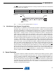
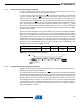
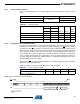
Figure 8-1. Enable Sector Protection
8.1.2 Disable Sector Protection Command
To disable the sector protection using the software controlled method, the CS
pin must first be
asserted as it would be with any other command. Once the CS
pin has been asserted, the
appropriate 4-byte sequence for the Disable Sector Protection command must be clocked in via
the input pin (SI). After the last bit of the command sequence has been clocked in, the CS
pin
must be deasserted after which the sector protection will be disabled. The WP
pin must be in the
deasserted state; otherwise, the Disable Sector Protection command will be ignored.
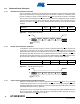
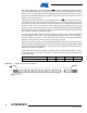
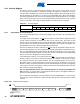
Figure 8-2. Disable Sector Protection
8.1.3 Various Aspects About Software Controlled Protection
Software controlled protection is useful in applications in which the WP
pin is not or cannot be
controlled by a host processor. In such instances, the WP
pin may be left floating (the WP pin is
internally pulled high) and sector protection can be controlled using the Enable Sector Protection
and Disable Sector Protection commands.
If the device is power cycled, then the software controlled protection will be disabled. Once the
device is powered up, the Enable Sector Protection command should be reissued if sector pro-
tection is desired and if the WP
pin is not used.
Command Byte 1 Byte 2 Byte 3 Byte 4
Enable Sector Protection 3DH 2AH 7FH A9H
Opcode
Byte 1
Opcode
Byte 2
Opcode
Byte 3
Opcode
Byte 4
CS
Each transition
represents 8 bits
SI
Command Byte 1 Byte 2 Byte 3 Byte 4
Disable Sector Protection 3DH 2AH 7FH 9AH
Opcode
Byte 1
Opcode
Byte 2
Opcode
Byte 3
Opcode
Byte 4
CS
Each transition
represents 8 bits
SI