
Owner's manual

19
Adesto AT45DB161E [DATASHEET]
8782D–DFLASH–11/2012
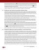
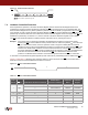
Figure 7-2. Disable Sector Protection
7.2 Hardware Controlled Protection
Sectors specified for protection in the Sector Protection Register and the Sector Protection Register itself can be
protected from program and erase operations by asserting the
WP pin and keeping the pin in its asserted state. The
Sector Protection Register and any sector specified for protection cannot be erased or programmed as long as the
WP
pin is asserted. In order to modify the Sector Protection Register, the WP pin must be deasserted. If the WP pin is
permanently connected to GND, then the contents of the Sector Protection Register cannot be changed. If the
WP pin is
deasserted or permanently connected to V
CC
, then the contents of the Sector Protection Register can be modified.
The
WP pin will override the software controlled protection method but only for protecting the sectors.
Example: If the sectors were not previously protected by the Enable Sector Protection command, then simply
asserting the
WP pin would enable the sector protection within the maximum specified t
WPE
time. When the
WP pin is deasserted, however, the sector protection would no longer be enabled (after the maximum
specified t
WPD
time) as long as the Enable Sector Protection command was not issued while the WP pin was
asserted. If the Enable Sector Protection command was issued before or while the
WP pin was asserted,
then simply deasserting the
WP pin would not disable the sector protection. In this case, the Disable Sector
Protection command would need to be issued while the
WP pin is deasserted to disable the sector
protection. The Disable Sector Protection command is also ignored whenever the
WP pin is asserted.
A noise filter is incorporated to help protect against spurious noise that may inadvertently assert or deassert the
WP pin.
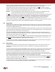
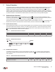
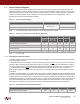
Figures 7-3 and Table 7-3 detail the sector protection status for various scenarios of the
WP pin, the Enable Sector
Protection command, and the Disable Sector Protection command.
Figure 7-3. WP Pin and Protection Status
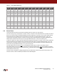
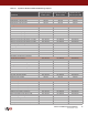
Table 7-3.
WP Pin and Protection Status
3Dh 2Ah 7Fh A9h
CS
Each transition represents eight bits
SI
Time
Period
WP Pin Enable Sector Protection Command
Disable Sector
Protection Command
Sector
Protection
Status
Sector
Protection
Register
1 High
Command Not Issued Previously X Disabled Read/Write
— Issue Command Disabled Read/Write
Issue Command — Enabled Read/Write
2 Low X X Enabled Read
3 High
Command Issued During Period 1 or 2 Not Issued Yet Enabled Read/Write
— Issue Command Disabled Read/Write
Issue Command — Enabled Read/Write
WP
12
3