
User Manual


6
AT45DB161B
2224E–DFLSH–10/02
BUFFER TO MAIN MEMORY PAGE PROGRAM WITHOUT BUILT-IN ERASE: A
previously er ased page within m ain memory can be programmed with the contents of
either buff er 1 or buffer 2. To sta rt the operation , an 8-bit op code, 88H for buffer 1 or
89H for buffer 2, must be followed by the two reserved bits, 12 address bits
(PA11 - PA0) that s pec ify the page in the m ain memo ry to be written , and te n addi ti ona l
don’t care bits. When a low-to-high transition occurs on the CS
pin, the part will program
the dat a stor ed in the buf fer in to t he s pe ci fied p age in the mai n m em or y. It i s n ec essa ry
that the page in ma in memory that is being programmed has been previous ly erased.
The programming of the page is internally self-timed and should take place in a m axi-
mum time of t
P
. During this time, the status register will indicate that the part is busy.
Successive page programming operations without doing a page erase are not rec om-
mended. In other words, changing bytes within a page from a “1” to a “0” during multiple
page programming operations without erasing that page is not recommended.
PA GE ER A SE : The op tional P age Erase command can be used to individua lly er ase
any page i n the m ain mem ory ar ray a llowing th e Buffer to Main M emory Page Pr ogra m
without B uilt-in Eras e com mand t o be uti lized a t a late r tim e. To perfo rm a Pag e Er ase,
an opcode of 81H must be loaded into the device, followed by two reserved bits,
12 address bits (PA11 - PA0), and ten don’t care bits. The 12 address bits are used to
specify which page of the memory array is to be erased. When a low-to-high transition
occurs on the CS
pin, the part will erase the selected page to 1s. The erase operation is
internally self-timed and should take place in a maximum time of t
PE
. During this time,
the status register will indicate that the part is busy.
BLOCK ERASE : A block of eigh t pages ca n be er ased at one tim e allowi ng the Bu ffer
to Main Me mor y P age Progr a m wi thou t B uil t-in Er as e command to be u til iz ed to re d uce
programming times when writing large amounts o f data to the devi ce. To perform a
Block Erase, an opcode of 50H must be loaded into the device, followed by two
reserve d bits, ni ne addr ess bi ts (PA 11 - PA3), and 13 don ’t car e bit s. The ni ne add ress
bits are used to s peci fy whic h bl ock of ei ght p ages is to be erased . Whe n a l ow-to -high
transition occurs on the CS
pin, the part will erase the selected block of eight pages to
1s. The erase operation is internally self-timed and should take place in a ma ximum
time of t
BE
. During this time, the status register will indicate that the part is busy.
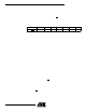
Block Erase Addressing
PA11 PA10 PA9 PA8 PA7 PA6 PA5 PA4 PA3 PA2 PA1 PA0 Block
000000000XXX0
000000001XXX1
000000010XXX2
000000011XXX3
•
•
•
•
•
•
•
•
•
•
•
•
•
•
•
•
•
•
•
•
•
•
•
•
•
•
•
•
•
•
•
•
•
•
•
•
•
•
•
111111100XXX508
111111101XXX509
111111110XXX510
111111111XXX511