
User guide
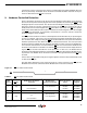
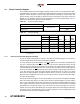
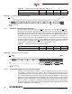
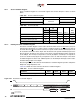
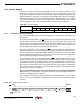
Table Of Contents
- Features
- 1. Description
- 2. Pin Configurations and Pinouts
- 3. Block Diagram
- 4. Memory Array
- 5. Device Operation
- 6. Read Commands
- 7. Program and Erase Commands
- 8. Sector Protection
- 9. Hardware Controlled Protection
- 10. Security Features
- 11. Additional Commands
- 12. Deep Power-down
- 13. “Power of 2” Binary Page Size Option
- 14. Manufacturer and Device ID Read
- 15. Command Tables
- 16. Power-on/Reset State
- 17. System Considerations
- 18. Electrical Specifications
- 19. Input Test Waveforms and Measurement Levels
- 20. Output Test Load
- 21. AC Waveforms
- 21.1 Waveform 1 – SPI Mode 0 Compatible (for Frequencies up to 66MHz)
- 21.2 Waveform 2 – SPI Mode 3 Compatible (for Frequencies up to 66MHz)
- 21.3 Waveform 3 – RapidS Mode 0 (FMAX = 66MHz)
- 21.4 Waveform 4 – RapidS Mode 3 (FMAX = 66MHz)
- 21.5 Utilizing the RapidS Function
- 21.6 Reset Timing
- 21.7 Command Sequence for Read/Write Operations for Page Size 256-Bytes (Except Status Register Read, Manufacturer and Device ID Read)
- 21.8 Command Sequence for Read/Write Operations for Page Size 264-Bytes (Except Status Register Read, Manufacturer and Device ID Read)
- 22. Write Operations
- 23. Read Operations
- 24. Detailed Bit-level Read Waveform – RapidS Serial Interface Mode 0/Mode 3
- 24.1 Continuous Array Read (Legacy Opcode E8H)
- 24.2 Continuous Array Read (Opcode 0BH)
- 24.3 Continuous Array Read (Low Frequency: Opcode 03H)
- 24.4 Main Memory Page Read (Opcode: D2H)
- 24.5 Buffer Read (Opcode D4H or D6H)
- 24.6 Buffer Read (Low Frequency: Opcode D1H or D3H)
- 24.7 Read Sector Protection Register (Opcode 32H)
- 24.8 Read Sector Lockdown Register (Opcode 35H)
- 24.9 Read Security Register (Opcode 77H)
- 24.10 Status Register Read (Opcode D7H)
- 24.11 Manufacturer and Device Read (Opcode 9FH)
- 25. Auto Page Rewrite Flowchart
- 26. Ordering Information
- 27. Packaging Information
- 28. Revision History
- 29. Errata

13
3596N–DFLASH–11/2012
AT45DB081D
If the device is power cycled, then the software controlled protection will be disabled. Once the
device is powered up, the Enable Sector Protection command should be reissued if sector pro-
tection is desired and if the
WP pin is not used.
9. Hardware Controlled Protection
Sectors specified for protection in the Sector Protection Register and the Sector Protection Reg-
ister itself can be protected from program and erase operations by asserting the
WPpinand
keeping the pin in its asserted state. The Sector Protection Register and any sector specified for
protection cannot be erased or reprogrammed as long as the
WP pin is asserted. In order to
modify the Sector Protection Register, the
WP pin must be deasserted. If the WP pin is perma-
nently connected to GND, then the content of the Sector Protection Register cannot be changed.
If the
WP pin is deasserted, or permanently connected to V
CC
, then the content of the Sector
Protection Register can be modified.
The WP pin will override the software controlled protection method but only for protecting the
sectors. For example, if the sectors were not previously protected by the Enable Sector Protec-
tion command, then simply asserting the WP pin would enable the sector protection within the
maximum specified t
WPE
time. When the WP pin is deasserted; however, the sector protection
would no longer be enabled (after the maximum specified t
WPD
time) as long as the Enable Sec-
tor Protection command was not issued while the WP pin was asserted. If the Enable Sector
Protection command was issued before or while the WP pin was asserted, then simply deassert-
ing the WP pin would not disable the sector protection. In this case, the Disable Sector
Protection command would need to be issued while the WP pin is deasserted to disable the sec-
tor protection. The Disable Sector Protection command is also ignored whenever the WP pin is
asserted.
A noise filter is incorporated to help protect against spurious noise that may inadvertently assert
or deassert the WP pin.
The table below details the sector protection status for various scenarios of the WP pin, the
Enable Sector Protection command, and the Disable Sector Protection command.
Figure 9-1. WP Pin and Protection Status
WP
12
3
Table 9-1. WP Pin and Protection Status
Time
Period
WP Pin
Enable Sector Protection
Command
Disable Sector
Protection Command
Sector Protection
Status
Sector
Protection
Register
1 High
Command Not Issued Previously
–
Issue Command
X
Issue Command
–
Disabled
Disabled
Enabled
Read/Write
Read/Write
Read/Write
2 Low X X Enabled Read Only
3 High
Command Issued During Period 1
or 2
–
Issue Command
Not Issued Yet
Issue Command
–
Enabled
Disabled
Enabled
Read/Write
Read/Write
Read/Write