
User Manual


24
AT45DB041E [ADVANCE DATASHEET]
8783B–DFLASH–11/2012
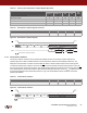
Table 8-3. Sector 0 (0a and 0b) Sector Lockdown Register Byte Value
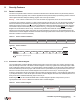
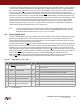
Table 8-4. Read Sector Lockdown Register Command
Figure 8-2. Read Sector Lockdown Register
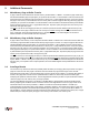
8.1.2 Freeze Sector Lockdown
The Sector Lockdown command can be permanently disabled, and the current sector lockdown state can be
permanently frozen so that no additional sectors can be locked down aside from those already locked down. Any
attempts to issue the Sector Lockdown command after the Sector Lockdown State has been frozen will be ignored.
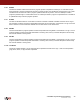
To issue the Freeze Sector Lockdown command, the
CS pin must be asserted and the opcode sequence of 34h, 55h,
AAh, and 40h must be clocked into the device. Any additional data clocked into the device will be ignored. When the
CS
pin is deasserted, the current sector lockdown state will be permanently frozen within a time of t
LOCK
. In addition, the SLE
bit in the Status Register will be permanently reset to a Logic 0 to indicate that the Sector Lockdown command is
permanently disabled.
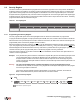
Table 8-5. Freeze Sector Lockdown
Figure 8-3. Freeze Sector Lockdown
Bit 7:6 Bit 5:4 Bit 3:2 Bit 1:0
Data
Value
Sector 0a
(Page 0-7)
Sector 0b
(Page 8-15) N/A N/A
Sectors 0a and 0b Unlocked 00 00 00 00 00h
Sector 0a Locked 11 00 00 00 C0h
Sector 0b Locked 00 11 00 00 30h
Sectors 0a and 0b Locked 11 11 00 00 F0h
Command Byte 1 Byte 2 Byte 3 Byte 4
Read Sector Lockdown Register 35h XXh XXh XXh
32h XX XX XX
Data
n
Data
n + 1
CS
Data
n + 7
SI
SO
Each transition represents eight bits
Command Byte 1 Byte 2 Byte 3 Byte 4
Freeze Sector Lockdown 34h 55h AAh 40h
34h 55h AAh 40h
CS
SI
Each transition represents eight bits