
Owner manual


16
3638K–DFLASH–11/2012
AT45DB021D
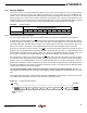
8.1.1 Sector Lockdown Register
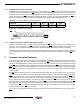
Sector Lockdown Register is a nonvolatile register that contains 8-bytes of data, as shown below:
Table 8-2. Sector Lockdown Register
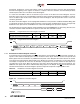
Table 8-3. Sector 0 (0a, 0b)
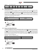
8.1.2 Reading the Sector Lockdown Register
The Sector Lockdown Register can be read to determine which sectors in the memory array are permanently
locked down. To read the Sector Lockdown Register, the CS pin must first be asserted. Once the CS pin has been
asserted, an opcode of 35H and 3 dummy bytes must be clocked into the device via the SI pin. After the last bit of
the opcode and dummy bytes have been clocked in, the data for the contents of the Sector Lockdown Register will
be clocked out on the SO pin. The first byte corresponds to sector 0 (0a, 0b) the second byte corresponds to sector
one and the last byte (byte eight) corresponds to sector seven. After the last byte of the Sector Lockdown Register
has been read, additional pulses on the SCK pin will simply result in undefined data being output on the SO pin.
Deasserting the CS pin will terminate the Read Sector Lockdown Register operation and put the SO pin into a
high-impedance state.
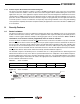
Table 8-4 details the values read from the Sector Lockdown Register.
Table 8-4. Sector Lockdown Register
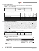
Figure 8-2. Read Sector Lockdown Register
Sector Number 0 (0a, 0b) 1 to 7
Locked
See Below
FFH
Unlocked 00H
0a 0b
Bit3,2
Data
Value
(Page 0-7) (Page 8-127)
Bit7,6 Bit5,4 Bit1,0
Sectors 0a, 0b Unlocked 00 00 00 00 00H
Sector 0a Locked (Page 0-7) 11 00 00 00 C0H
Sector 0b Locked (Page 8-127) 00 11 00 00 30H
Sectors 0a, 0b Locked (Page 0-127) 11 11 00 00 F0H
Command Byte 1 Byte 2 Byte 3 Byte 4
Read Sector Lockdown Register 35H xxH xxH xxH
Note: xx = Dummy Byte
Opcode X X X
Data Byte
n
Data Byte
n + 1
CS
Data Byte
n + 3
SI
SO
Each transition
represents 8 bits