
Owner's manual

13
3639J–DFLASH–11/2012
AT45DB011D
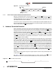
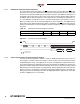
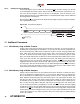
9.1 Sector Protection Register
The nonvolatile Sector Protection Register specifies which sectors are to be protected or unpro-
tected with either the software or hardware controlled protection methods. The Sector Protection
Register contains 4-bytes of data, of which byte locations 0 through 3 contain values that specify
whether sectors 0 through 3 will be protected or unprotected. The Sector Protection Register is
user modifiable and must first be erased before it can be reprogrammed. Table 9-3 illustrates the
format of the Sector Protection Register.
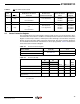
Note: 1. The default value for bytes 0 through 3 when shipped from Adesto is 00H.
x = don’t care.
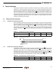
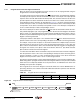
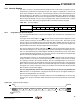
Table 9-1. WP Pin and Protection Status
Time
Period
WP Pin
Enable Sector Protection
Command
Disable Sector
Protection Command
Sector Protection
Status
Sector
Protection
Register
1 High
Command Not Issued Previously
–
Issue Command
X
Issue Command
–
Disabled
Disabled
Enabled
Read/Write
Read/Write
Read/Write
2 Low X X Enabled Read Only
3 High
Command Issued During Period 1
or 2
–
Issue Command
Not Issued Yet
Issue Command
–
Enabled
Disabled
Enabled
Read/Write
Read/Write
Read/Write
Table 9-2. Sector Protection Register
Sector Number 0 (0a, 0b) 1 to 3
Protected
See Table 9-3
FFH
Unprotected 00H
Table 9-3. Sector 0 (0a, 0b)
0a 0b
Bit3,2
Data
Value
(Page 0-7) (Page 8-127)
Bit7,6 Bit5,4 Bit1,0
Sectors 0a, 0b Unprotected 00 00 xx xx 0xH
Protect Sector 0a 11 00 xx xx CxH
Protect Sector 0b (Page 8-127) 00 11 xx xx 3xH
Protect Sectors 0a (Page 0-7), 0b
(Page 8-127)
(1)
11 11 xx xx FxH