
User Manual


39
9570H–AT42–02/10
AT42QT1110-MZ/AT42QT1110-AZ
8.5 SPI Bus Specifications
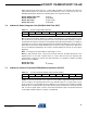
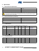
8.5.1 General Specifications
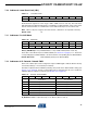
8.5.2 Full SPI Mode
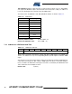
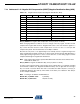
8.5.3 Quick SPI Mode
Parameter Specification
Address space 8-bit
Maximum clock rate 1.5 MHz
Minimum low clock period 333 ns
Minimum high clock period 333 ns
Clock idle High
Setup on Leading (falling) edge
Clock out on Trailing (rising) edge
SPI Enable delay (SS low to SCK low) 1 µs
Parameter Specification
Time between bytes 150 µs
Time between communications
Generally 150 µs; longer delays required to implement some commands, as follows:
• Send Setups: 150 µs after all setup bytes are returned
• Calibrate All: 150 µs
• Calibrate Key: 150 µs
• Reset: 160 ms
• Sleep: 150 µs after a low signal is applied to SS
or CHANGE to wake the device
• Store to EEPROM: 200 ms
• Restore from EEPROM: 150 ms
• Erase EEPROM: 50 ms
• Recover EEPROM: 50 ms
Parameter Specification
Time between bytes 50 µs
Time between communications
Generally 50 µs, except for the following:
• Store to EEPROM: 200 ms
• Switch to Full SPI: 150 µs