
User Manual


35
9570H–AT42–02/10
AT42QT1110-MZ/AT42QT1110-AZ
7.14 Address 17: LED Fade/Key to LED
FADE: enables/disables fading for all LEDs. This is a global setting; either all LEDs fade, or
none of them.
0 = disable (no fade).
1 = enable fading on and off.
LED_n: activates the LED output for the corresponding key output DETECTn (where n is 0–6).
1 = enables the “Detect” output to follow the status of the corresponding key.
0 = disable this function, in which case the “Detect” pin will always output its “Out of Detect”
PWM (see Section 7.12 on page 33).
Default FADE value: 0 (disabled)
Default LED_n value: 1 (enabled)
7.15 Address 18: LED Latch
LATCH_n: enables/disables latching of the LED for the corresponding key output DETECTn
(where n is 0–6).
1 = enables latching. When latching is enabled for a given LED, the LED toggles its state each
time the key is touched.
0 = disables latching.
Note that bit 7 is reserved and should be set to zero.
Default LATCH_n value: 0x00 (latch disabled)
7.16 Addresses 19–29: Negative Threshold (NTHR)/Negative Hysteresis (NHYST)
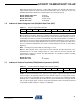
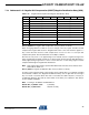
Table 7-14. LED Fade/Key to LED
Address Bit 7 Bit 6 Bit 5 Bit 4 Bit 3 Bit 2 Bit 1 Bit 0
17 FADE LED_6 LED_5 LED_4 LED_3 LED_2 LED_1 LED_0
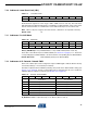
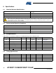
Table 7-15. LED Latch
Address Bit 7 Bit 6 Bit 5 Bit 4 Bit 3 Bit 2 Bit 1 Bit 0
18
0 LATCH_6 LATCH_5 LATCH_4 LATCH_3 LATCH_2 LATCH_1 LATCH_0
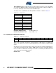
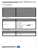
Table 7-16. Negative Threshold/Negative Hysteresis
Address Bit 7 Bit 6 Bit 5 Bit 4 Bit 3 Bit 2 Bit 1 Bit 0
19 KEY_0_NTHR KEY_0_NHSYT
20 KEY_1_NTHR KEY_1_NHSYT
21 KEY_2_NTHR KEY_2_NHSYT
22 KEY_3_NTHR KEY_3_NHSYT
23 KEY_4_NTHR KEY_4_NHSYT
24 KEY_5_NTHR KEY_5_NHSYT