
User Manual


33
9570H–AT42–02/10
AT42QT1110-MZ/AT42QT1110-AZ
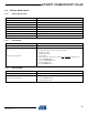
7.10 Address 6: Lower Burst Limit (LBL)
Normal QTouch signals are in the range of 100 to 1000 counts for each key. The lower burst
limit determines the minimum signal that is considered as a valid acquisition. If the count is lower
than the lower burst limit, it is considered not to be valid and the key is set to an Error state.
Note: Where a key has a signal of less than the LBL, a detection is not reported on that key.
Default value: 18
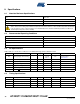
7.11 Addresses 7–8: AKS Mask
AKS_n (AKS Mask): 0 = key n AKS disabled, 1 = key n AKS enabled (where n is 0–10).
These bits control which keys have AKS enabled (see Section 3 on page 8). A “1” means the
corresponding key has AKS enabled; a “0” means that the corresponding key has AKS disabled.
Default AKS mask: 0x07 and 0xFF (all keys have AKS enabled)
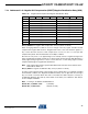
7.12 Addresses 9–15: Detect0 – Detect6 PWM
Each of the 7 detect pins can be configured to output a PWM signal to indicate whether the key
is touched (in detect) or not touched (out of detect).
The Detect outputs must be enabled by selecting 7-key mode in the “Device Mode” setting (see
Section 7.4 on page 29), and the corresponding “Key to LED” bits must be set to enable the
individual “Detect” outputs for each key (see Section 7.14 on page 35).
IN_DETECTn: PWM to output when key n is “In Detect” (where n is 0–7).
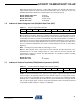
Table 7-9. Lower Burst Limit
Address Bit 7 Bit 6 Bit 5 Bit 4 Bit 3 Bit 2 Bit 1 Bit 0
6LBL
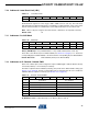
Table 7-10. AKS Mask
Address Bit 7 Bit 6 Bit 5 Bit 4 Bit 3 Bit 2 Bit 1 Bit 0
7 AKS_10 AKS_9 AKS_8
8 AKS_7 AKS_6 AKS_5 AKS_4 AKS_3 AKS_2 AKS_1 AKS_0
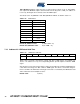
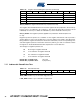
Table 7-11. Detect0 – Detect6 PWM
Address Bit 7 Bit 6 Bit 5 Bit 4 Bit 3 Bit 2 Bit 1 Bit 0
9 IN_DETECT0 OUT_DETECT0
10 IN_DETECT1 OUT_DETECT1
11 IN_DETECT2 OUT_DETECT2
12 IN_DETECT3 OUT_DETECT3
13 IN_DETECT4 OUT_DETECT4
14 IN_DETECT5 OUT_DETECT5
15 IN_DETECT6 OUT_DETECT6