
User Manual


29
9570H–AT42–02/10
AT42QT1110-MZ/AT42QT1110-AZ
7.2 Setting Individual Settings
To set up an individual setup value, the host sends the command listed under the “Set
Command” column in Table 7-1, followed by a byte of data.
For details of the communication flow, see Section4.1 on page10.
7.3 Setting All the Setups
The host can send all 42 bytes of setup data to the QT1110 as a block using the Send Setups
command. See Section 5.2 on page 22 for details.
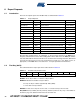
7.4 Address 0: Device Mode
The Device Mode controls the overall operation of the device: number of keys, acquisition
method, timing and trigger mechanism.
KEY_AC: selects the trigger source to start key acquisition; 0 = SYNC pin, 1 = timed.
MODE: selects 7-key or 11-key mode; 0 = default 7-key mode, 1 = 11-key mode.
SIGNAL: selects serial or parallel acquisition of keys signals; 0 = serial, 1 = parallel.
SYNC: selects the trigger type when SYNC Pin is selected as the trigger to start key acquisition.
0 = Level Acquisition starts when a “0” is read at the SYNC pin. If the pin is held
low, the QT1110 operates in “Free run” mode (that is, it will not sleep in
between acquisitions, but start again immediately).
1 = Edge Acquisition starts when a rising edge is detected at the SYNC pin.
When acquisition and post-processing are completed, the device
sleeps until another rising edge is detected at the SYNC pin.
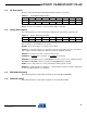
32 Key1 Negative Drift Compensation (NDRIFT)/Negative Recalibration Delay (NRD) 0xB1 0xF1
33 Key2 Negative Drift Compensation (NDRIFT)/Negative Recalibration Delay (NRD) 0xB2 0xF2
34 Key3 Negative Drift Compensation (NDRIFT)/Negative Recalibration Delay (NRD) 0xB3 0xF3
35 Key4 Negative Drift Compensation (NDRIFT)/Negative Recalibration Delay (NRD) 0xB4 0xF4
36 Key5 Negative Drift Compensation (NDRIFT)/Negative Recalibration Delay (NRD) 0xB5 0xF5
37 Key6 Negative Drift Compensation (NDRIFT)/Negative Recalibration Delay (NRD) 0xB6 0xF6
38 Key7 Negative Drift Compensation (NDRIFT)/Negative Recalibration Delay (NRD) 0xB7 0xF7
39 Key8 Negative Drift Compensation (NDRIFT)/Negative Recalibration Delay (NRD) 0xB8 0xF8
40 Key9 Negative Drift Compensation (NDRIFT)/Negative Recalibration Delay (NRD) 0xB9 0xF9
41 Key10 Negative Drift Compensation (NDRIFT)/Negative Recalibration Delay (NRD) 0xBA 0xFA
Table 7-1. Memory Map (Continued)
Address Function Set Command Get Command
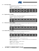
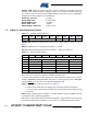
Table 7-2. Device Mode
Address Bit 7 Bit 6 Bit 5 Bit 4 Bit 3 Bit 2 Bit 1 Bit 0
0 KEY_AC MODE SIGNAL SYNC REPEAT_TIME