
User Manual


27
9570H–AT42–02/10
AT42QT1110-MZ/AT42QT1110-AZ
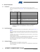
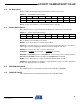
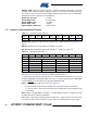
6.11 Detect Output States (0xC6)
This command returns a byte that indicates which PWM signal is applied to each DETECT pin.
DET_n: 0 = “Out of Detect” PWM is output, 1 = the “In Detect” PWM is output.
Note: Note: During “LED Detect Hold Time” or “LED Fade”, the report indicates the new state
of the DETECT pin. For example, if the DETECT output is in “LED Detect Hold Time”
before switching to “Out of Detect” PWM, the reported state is “0”.
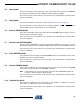
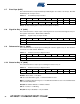
6.12 Last Command (0xC7)
This command returns the previous 1-byte command that was received from the host. Note that
this command does not return itself.
6.13 Setups (0xC8)
This command returns the 42 bytes of the setups table, starting with address 0, with the most
significant bit first.
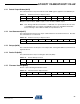
6.14 Device ID (0xC9)
This command returns 1 byte containing the device ID (0x57).
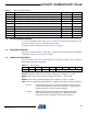
6.15 Firmware Version (0xCA)
Returns 1 byte containing the firmware version.
Table 6-9. Reference for Key “k” Report Format
Bit 7 Bit 6 Bit 5 Bit 4 Bit 3 Bit 2 Bit 1 Bit 0
Byte 0
DET_6 DET_5 DET_4 DET_3 DET_2 DET_1 DET_0
Table 6-10. Reference for Key “k” Report Format
Bit 7 Bit 6 Bit 5 Bit 4 Bit 3 Bit 2 Bit 1 Bit 0
Byte 0 Last Command
Table 6-11. Device ID Report Format
Bit 7 Bit 6 Bit 5 Bit 4 Bit 3 Bit 2 Bit 1 Bit 0
Byte 0 Device ID = 0x57
Table 6-12. Firmware Version Report Format
Bit 7 Bit 6 Bit 5 Bit 4 Bit 3 Bit 2 Bit 1 Bit 0
Byte 0 Major Version Minor Version