
User Manual


16
9570H–AT42–02/10
AT42QT1110-MZ/AT42QT1110-AZ
4.1.6 Quick SPI Mode
4.1.6.1 Introduction
In Quick SPI Mode, the QT1110 sends a 7-byte key report at each exchange. No host
commands are required over SPI in this mode; the host clocks the data bytes out in sequence.
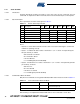
4.1.6.2 Quick SPI Report
The 7 report bytes are in the format given in Table 4-1.
where:
• Byte 0 is a counter that increments from 0 to 254 on successive exchanges to confirm that
firmware is operating correctly.
• Bytes 1 – 3 indicate the detect status of channels 0 – 3, 4 – 7 and 8 – 10 respectively (two
bits per channel), as follows:
– 00 = Channel not in detect
– 01 = Channel in detect
– 10 = Not Allowed
– 11 = Invalid Signal (Channel disabled)
• Bytes 4 – 6 indicate the error status of channels 0 – 3, 4 – 7 and 8 – 10 respectively (two bits
per channel), as follows:
–00 = No error
– 01 = Not allowed
– 10 = Error on channel
– 11 = Invalid signal (channel disabled)
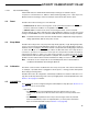
4.1.6.3 Commands in Quick SPI Mode
Only two host commands are recognized under Quick SPI mode. These are shown in Table 4-2.
CRC checking is not implemented in Quick SPI mode for host commands or return data.
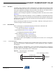
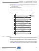
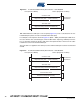
Table 4-1. Device Status Report Format
Byte Description Bit 7 Bit 6 Bit 5 Bit 4 Bit 3 Bit 2 Bit 1 Bit 0
0 Counter Counter – increments from 0 to 255
1 Detect status, channels 0 – 3 Channel 3 Channel 2 Channel 1 Channel 0
2 Detect status, channels 4 – 7 Channel 7 Channel 6 Channel 5 Channel 4
3 Detect status, channels 8 – 10
Reserved Channel 10 Channel 9 Channel 8
4 Error status, channels 0 – 3 Channel 3 Channel 2 Channel 1 Channel 0
5 Error status, channels 4 – 7 Channel 7 Channel 6 Channel 5 Channel 4
6 Error status, channels 8 – 10
Reserved Channel 10 Channel 9 Channel 8
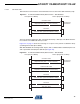
Table 4-2. Host Commands in Quick SPI Mode
Command Code Purpose
Store to EEPROM 0x0A
Allows for “Quick SPI mode” to be stored as the
default start-up mode
Enable Full SPI 0x36 Enables full SPI mode