
Manual
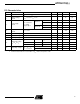
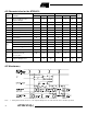
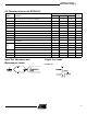
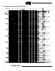
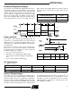
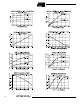
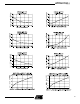
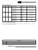
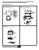
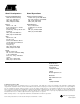
Table Of Contents
- Pin Configurations
- DC and AC Operating Conditions
- Features
- Logic Diagram
- Description
- Absolute Maximum Ratings*
- Logic Options
- Output Options
- DC Characteristics
- AC Characteristics for the AT22LV10
- AC Waveforms(1)
- AC Characteristics for the AT22LV10L
- Input Test Waveforms and Measurement Levels
- Output Test Loads
- Functional Logic Diagram AT22LV10(L)
- Preload of Registered Outputs
- Power-up Reset
- Pin Capacitance
- Erasure Characteristics
- Ordering Information
- Using “C” Product for Industrial
AT22LV10(L)
11
Packaging Information
.045(1.14) X 45°
PIN NO. 1
IDENTIFY
.032(.813)
.026(.660)
.050(1.27) TYP
.300(7.62) REF SQ
.045(1.14) X 30° - 45°
.022(.559) X 45° MAX (3X)
.012(.305)
.008(.203)
.021(.533)
.013(.330)
.430(10.9)
.390(9.91)
SQ
.043(1.09)
.020(.508)
.120(3.05)
.090(2.29)
.180(4.57)
.165(4.19)
.456(11.6)
.450(11.4)
.495(12.6)
.485(12.3)
SQ
SQ
1.27(32.3)
1.25(31.7)
PIN
1
.266(6.76)
.250(6.35)
.090(2.29)
MAX
.005(.127)
MIN
.070(1.78)
.020(.508)
.023(.584)
.014(.356)
.065(1.65)
.040(1.02)
.325(8.26)
.300(7.62)
0
15
REF
.400(10.2) MAX
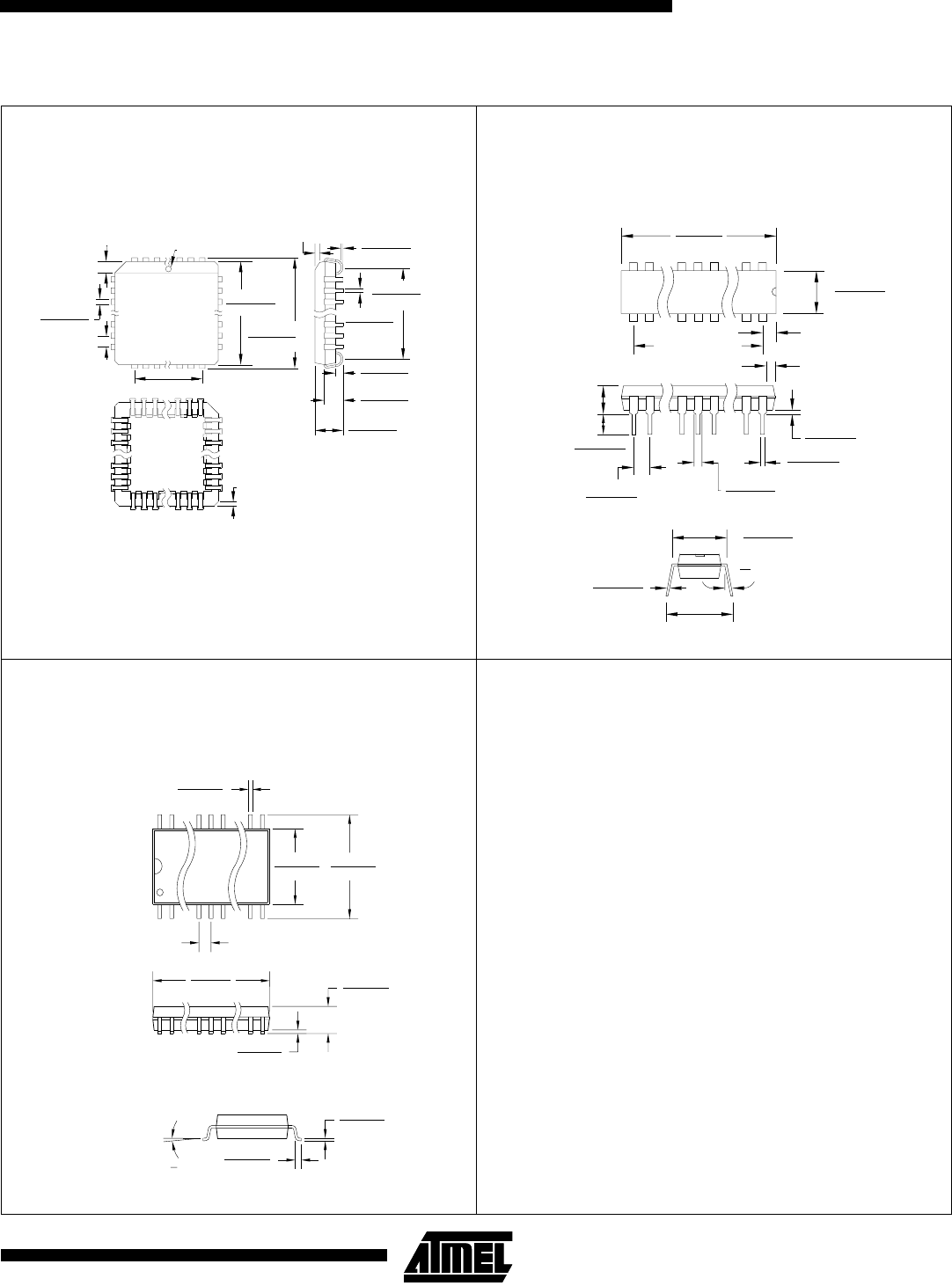
.012(.305)
.008(.203)
.110(2.79)
.090(2.29)
.151(3.84)
.125(3.18)
SEATING
PLANE
.200(5.06)
MAX
1.100(27.94) REF
.020(.508)
.013(.330)
.299(7.60)
.291(7.39)
.420(10.7)
.393(9.98)
.105(2.67)
.092(2.34)
.050(1.27) BSC
.616(15.6)
.598(15.2)
.012(.305)
.003(.076)
.013(.330)
.009(.229)
.050(1.27)
.015(.381)
8
0
REF
PIN 1 ID
28J, 28-lead, Plastic J-leaded Chip Carrier (PLCC)
Dimensions in Inches and (Millimeters)
JEDEC STANDARD MS-018 AB
24P3, 24-lead, 0.300” Wide. Plastic
Dual Inline Package (PDIP)
Dimensions in Inches and (Millimeters)
JEDEC STANDARD MS-011 AB
24S, 24-lead, 0.300” Wide, Plastic Gull-Wing Small
Outline (SOIC)
Dimensions in Inches and (Millimeters)