
Owner's manual


Preliminary
APR6016 Data Sheet
Page 14 Voice Recording & Playback Device
Revision 1.0
ment needs to be selected, and do so before the SAC si
g
nal
returns hi
g
h. Failin
g
to specif
y
the next command before the
current se
g
ment is exhausted
(
either durin
g
recordin
g
or
pla
y
back
)
will result in a noticeable
g
ap durin
g
pla
y
back or
recordin
g
.
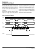
The /BUSY pin indicates when the device is performin
g
either
a pla
y
, record, DIG_WRITE, DIG_READ or fast forward func-
tion. The host microprocessor can monitor the bus
y
pin to
confirm the status of these commands. The /BUSY pin is nor-
mall
y
hi
g
h and
g
oes low while the device is bus
y
. The low
time is
g
overned b
y
the len
g
th of recordin
g
or pla
y
back spec-
ified b
y
the user.
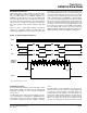
Sampling Rate and Voice Quality
The N
yq
uist Samplin
g
Theorem re
q
uires that the hi
g
hest fre-
q
uenc
y
component a samplin
g
s
y
stem can accommodate
without the introduction of aliasin
g
errors is e
q
ual to half the
samplin
g
fre
q
uenc
y
. The APR6016 automaticall
y
filters its
input, based on the selected samplin
g
fre
q
uenc
y
, to meet this
re
q
uirement.
Hi
g
her samplin
g
rates increase recordin
g
bandwidth, and
hence voice
q
ualit
y
, but also use more memor
y
cells for the
same amount of recordin
g
time. The APR6016 ccommo-
dates samplin
g
rates as hi
g
h as 8kHz.
Lower samplin
g
rates use less memor
y
cells and effectivel
y
increase the duration capabilities of the device, but also
reduce recordin
g
bandwidth. The APR6016 allows samplin
g
rates as low as 4 kHz.
Desi
g
ners can thus control the
q
ualit
y
/duration trade-off b
y
controllin
g
the samplin
g
fre
q
uenc
y
. Samplin
g
fre
q
uenc
y
can
be controlled b
y
usin
g
the PWRUP command. This command
can chan
g
e samplin
g
fre
q
uenc
y
re
g
ardless of whether the
internal oscillator is used or an external clock is used.
The APR6016 derives its samplin
g
clock from one of two
sources: internal or external. If a clockin
g
si
g
nal is present on
the EXTCLK input the device will automaticall
y
use this si
g
nal
as the samplin
g
clock source. If no input is present on the
EXTCLK input the device automaticall
y
defaults to the inter-
nal clock source. When the EXTCLK pin is not used it should
be tied to GND.
An internal clock divider is provided so that external clock si
g
-
nals can be divided down to a desired samplin
g
rate. This
allows hi
g
h fre
q
uenc
y
si
g
nals of up to 10 MHz to be fed into
the EXTCLK pin. Usin
g
this feature simplifies desi
g
ns b
y
allowin
g
use of a clock alread
y
present in the s
y
stem, as
opposed to havin
g
to
g
enerate or externall
y
divide down a
custom clock. Details for pro
g
ramin
g
the clock divider are
described in the SPI interface section under the PWRUP
para
g
raph.
The default power up condition for the APR6016 is to use the
internal oscillator at a samplin
g
fre
q
uenc
y
of 6.4 kHz.
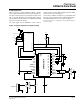
Storage Technology
The APR6016 stores voice si
g
nals b
y
samplin
g
incomin
g
voice data and storin
g
the sampled si
g
nals directl
y
into
FLASH memor
y
cells. Each FLASH cell can support volta
g
e
ran
g
es from 1 to 256 levels. These 256 discrete volta
g
e lev-
els are the e
q
uivalent of ei
g
ht
(
2
8
=256
)
bit binar
y
encoded
values. Durin
g
pla
y
back the stored si
g
nals are retrieved from
memor
y
, smoothed to form a continuous si
g
nal and finall
y
amplified before bein
g
fed to an external speaker amplifier.
Squelch
The APR6016 is e
q
uipped with an internal s
q
uelch feature.
The S
q
uelch circuit automaticall
y
attenuates the output si
g
nal
b
y
6 dB durin
g
q
uiet passa
g
es in the pla
y
back material. Mut-
in
g
the output si
g
nal durin
g
q
uiet passa
g
es helps eliminate
back
g
round noise. Back
g
round noise ma
y
enter the s
y
stem
in a number of wa
y
s includin
g
: present in the ori
g
inal si
g
nal,
natural noise present in some power amplifier desi
g
ns, or
induced throu
g
h a poorl
y
filtered power suppl
y
.
The response time of the s
q
uelch circuit is controlled b
y
the
time constant of the capacitor connected to the SQLCAP pin.
The recommended value of this capacitor is 1.0 uF. The
s
q
uelch feature can be disabled b
y
connectin
g
the SQLCAP
pin to VCC.
The active low output /SQLOUT
g
oes low whenever the inter-
nal s
q
uelch activates. This si
g
nal can be used to s
q
uelch the
output power amplifier. S
q
uelchin
g
the output amplifier
results in further reduction of noise; especiall
y
when the
power amplifier is runnin
g
at hi
g
h
g
ain & loud volumes.