
Owner's manual


Tables (Continued)
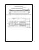
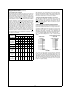
TABLE VI. Status Register
Status Bit
DB0 DB1 DB2 DB3 DB4 DB5 DB6 DB7 DB8
Location
Status Bit PU PD Cal 12 or 13 16 or 17 Sign Justification Test Mode
Device Status DO Output Format Status
‘‘High’’ ‘‘High’’ ‘‘High’’ Not used ‘‘High’’ ‘‘High’’ ‘‘High’’ When ‘‘High’’ When ‘‘High’’
indicates a indicates a indicates an indicates a 12 indicates a 16 indicates that the the device is
Power Up Power Down Auto-Cal or 13 bit or 17 bit the sign bit is conversion in test mode.
Sequence is Sequence is Sequence is format format included. result will be When ‘‘Low’’
Function
in progress in progress in progress When ‘‘Low’’ output MSB the device is
the sign bit is first. When in user mode.
not included. ‘‘Low’’ the
result will be
output LSB
first.
Application Hints
1.0 DIGITAL INTERFACE
1.1 Interface Concepts
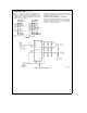
The example in
Figure 5
shows a typical sequence of
events after the power is applied to the ADC12130/2/8:
TL/H/12079–32
FIGURE 5. Typical Power Supply Power Up Sequence
The first instruction input to the A/D via DI initiates Auto Cal.
The data output on DO at that time is meaningless and is
completely random. To determine whether the Auto Cal has
been completed, a read status instruction is issued to the
A/D. Again the data output at that time has no significance
since the Auto Cal procedure modifies the data in the output
shift register. To retrieve the status information, an addition-
al read status instruction is issued to the A/D. At this time
the status data is available on DO. If the Cal signal in the
status word, is low Auto Cal has been completed. There-
fore, the next instruction issued can start a conversion. The
data output at this time is again status information. To keep
noise from corrupting the A/D conversion, status can not be
read during a conversion. If CS
is strobed and is brought low
during a conversion, that conversion is prematurely ended.
EOC can be used to determine the end of a conversion or
the A/D controller can keep track in software of when it
would be appropriate to comnmunicate to the A/D again.
Once it has been determined that the A/D has completed a
conversion, another instruction can be transmitted to the
A/D. The data from this conversion can be accessed when
the next instruction is issued to the A/D.
Note, when CS
is low continuously it is important to transmit
the exact number of SCLK cycles, as shown in the timing
diagrams. The Data Out Format sets the number of SCLK
cycles required in the next I/O cycle. A 12-bit no sign format
will require 12 SCLKs to be transmitted; a 12-bit plus sign
format will require 13 SCLKs to be transmitted, etc. Not do-
ing so will desynchronize the serial communication to the
A/D. (See Section 1.3.)
1.2 Changing Configuration
The configuration of the ADC12130/2/8 on power up de-
faults to 12-bit plus sign resolution, 12- or 13-bit MSB First,
10 CCLK acquisition time, user mode, no Auto Cal, no Auto
Zero, and power up mode. Changing the acquisition time
and turning the sign bit on and off requires an 8-bit instruc-
tion to be issued to the ADC. This instruction will not start a
conversion. The instructions that select a multiplexer ad-
dress and format the output data do start a conversion.
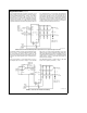
Fig-
ure 6
describes an example of changing the configuration of
the ADC12130/2/8.
During I/O sequence 1, the instruction on DI configures the
ADC12130/2/8 to do a conversion with 12-bit
a
sign reso-
lution. Notice that when the 6 CCLK Acquisition and Data
Out without Sign instructions are issued to the ADC, I/O
sequences 2 and 3, a new conversion is not started. The
data output during these instructions is from conversion N
which was started during I/O sequence 1. The Configura-
tion Modification timing diagram describes in detail the se-
quence of events necessary for a Data Out without Sign,
Data Out with Sign, or 6/10/18/34 CCLK Acquisition time
mode selection. Table IV describes the actual data neces-
sary to be input to the ADC to accomplish this configuration
modification. The next instruction, shown in
Figure 6
, issued
to the A/D starts conversion N
a
1 with 16-bit format with 12
bits of resolution formatted MSB first. Again the data output
during this I/O cycle is the data from conversion N.
The number of SCLKs applied to the A/D during any con-
version I/O sequence should vary in accord with the data
out word format chosen during the previous conversion I/O
sequence. The various formats and resolutions available
are shown in Table I. In
Figure 6
, since 16-bit without sign
MSB first format was chosen during I/O sequence 4, the
number of SCLKs required during I/O sequence 5 is 16. In
the following I/O sequence the format changes to 12-bit
without sign MSB first; therefore the number of SCLKs re-
quired during I/O sequence 6 changes accordingly to 12.
1.3 CS
Low Continuously Considerations
When CS is continuously low, it is important to transmit the
exact number of SCLK pulses that the ADC expects. Not
doing so will desynchronize the serial communications to
the ADC. When the supply power is first applied to the ADC,
26