
Owner manual
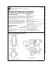
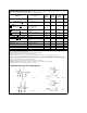
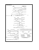
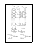

Timing Diagrams
TL/H/5501–7
FIGURE 2. RD Mode (Pin 7 is Low)
Note: On power-up the state of INT can be high or low.
TL/H/5501–8
FIGURE 3a. WR-RD Mode (Pin 7 is High and t
RD
k
t
I
)
TL/H/5501–9
FIGURE 3b. WR-RD Mode (Pin 7 is High and t
RD
l
t
I
)
TL/H/5501–10
FIGURE 4. WR-RD Mode (Pin 7 is High)
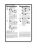
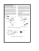
Stand-Alone Operation
5