
User Manual
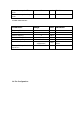


• Frequency Band
868-868.6MHz, 910-924MHz
11 channels
• Power
+3.3V ±0.3V from carrier board, 3.0V to 3.6V from
battery pack
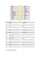
• Interfaces
40-pin surface-mount 2x20 1.27mm pitch
• RF
40kbps BPSK DSSS @915MHz
20kbps BPSK DSSS @868MHz
• Dimensions
46.5 mm x 26 mm x 10 mm
• Antenna Interface
50-Ohm MMCX female or UFL connector
• Operating Temperature Range
-40ºC to +85ºC
• Indicators
Two LEDs, one red, one yellow (DS1, DS2)
• Current Consumption
600µA Sleep
170mA TX @ Medium Level 25℃
35mA RX/Ideal
• RF receive sensitivity -100dBm at at 1% packet error rate for a 20 byte
payload.
• Output Power EIRP
Up to 20dBm
1.3 Abbreviations and Acronyms
ADC Analog-to -Digital Converter
API Application Programming Interface
BPSK Binary Phase-Shift Keying modulation scheme
DC Direct Current
DTR Data Terminal Ready
EEPROM Electrically Erasable Programmable Read-Only Memory
ESD Electrostatic Discharge
GPIO General Purpose Input/Output
HVAC Heating, Ventilating and Air Conditioning
HW Hardware
I2C Inter-Integrated Circuit
IEEE Institute of Electrical and Electrionics Engineers
IRQ Interrupt Request
ISM Industrial, Scientific and Medical radio band
JTAG
Digital interface for debugging of embedded device, also known as IEEE 1149.1 standard
interface
MAC Medium Access Control layer
MCU