
User's Manual


Channel Frequencies
These channels are equivalent to IEEE 802.15.4 channels 11 to 26.
RM2420 Channel Frequencies (GHz)
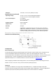
Pin Layout
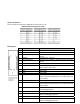
Pin ATmega 128/64 Pin Name Description
1 GND Digital GND
2 GND Digital GND
3 PD3 (TXD1/INT3) EmberNet stack defaults to Alternate Function TX UART
(TXD1)
4 nRESET External reset, active low
5 PD2 (RXD1/INT2) EmberNet stack defaults to Alternate Function RX UART
(Rxd1)
6 PG1 (nRD) General purpose I/O
7 +3.3V out External power pin used to run custom external sensors
and/or devices; 20mA max
8 +3.3V in Input power from carrier boards
9 GND Digital GND
10 GND Digital GND
11 PD1 (SDA/INT1) General purpose I/O; EmberNet defaults signal as an
output connected to EM2 (button 1) on carrier board (with
J11 installed)
12 PG0 (nWR) General purpose I/O
13 PD0 (SDl/INT0) General purpose I/O; EmberNet defaults signal as an
output connected to EM1 (button 0) on carrier board (with
J10 installed)
14 PC2 Dedicated connection to red LED (D55 on carrier board)
for debugging purposes
15 PB7 (OC2/OC1C) General purpose I/O
16 PC3 Dedicated connection to yellow LED (DS4 on carrier
board) for debugging purposes
17 PB6 General purpose I/O
18 PC5 Dedicated connection to orange LED (DS2 on carrier
board) for debugging purposes