
User's Manual


RAEMesh2 User Manual
Doc.No:
Originator: kren
Page 3 of 21
Data: 2014-3-18
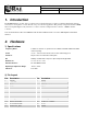
1. Introduction
The RAEMesh Radio module offers a complete microcontroller/transceiver solution Containing all hardware features
necessary for development of a low data-rate, low-power wireless application. The primary components include an IEEE
802.15.4 compliant Zigbee-ready transceiver , a microcontroller, a 40-pin interface connector, a MMCS antenna
connector,
This documentation describes the RAEMesh radio module hardware interface as well as RAE System’s Command
Interface.
2. Hardware
1) Specifications
Frequency Band
2.4Ghz: 15 channels of operation in the 2.4GHz world wide ISM band. 5MHz
channel spacing.
Power
+3.3V + .3V from carrier board, 3.0V to 3.6V from battery pack
Interfaces
40-pin surface-mount 2x20 1.27mm pitch
RF
250kbps OQPSK Direct Sequence Spread Spectrum @2.4GHz
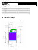
Dimensions
46.5 mm x 26 mm x 10 mm
Antenna Interface
50-Ohm MMCX female
Operating Temperature Range
-40ºC to +85ºC
Indicators
Two LEDs
2) Pin Layout
Pin
Description
Pin
Description
1
DGND
2
DGND
3
nRESET
4
DGND
5
TXD1
6
TXD0/Bootload.
7
RXD1
8
RXD0
9
GPIO0
10
GPIO/LED2
11
GPIO1
12
GPIO/LED3
13
GPIO2
14
GPIO/LED4
15
GPIO3
16
GPIO/LED5
17
TEMP_E/GPIO4
18
GPIO/PS_CS
19
WakeUp/GPIO5
20
GPIO/PS_FRAME
21
BUZZER/GPIO6
22
+3.3V
23
GPIO7/PS_DIR
24
AGND