
User's Manual


Mounting the IDUs Chapter 3
RADWIN 1000/2000 User Manual Version 2.12 3-9
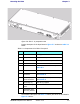
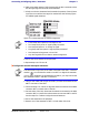
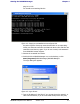
Figure 3-8: IDU-C - A perspective view
Further description of the keyed items in figure 3-7 is shown in table 3-1
below:
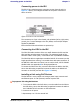
The Indicator LEDs (Item A in table 3-1 above) are shown in more detail in
figure 3-9 below:
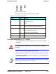
Table 3-1: Components of an IDU-C front panel
Key Label Remarks
A Indicator LEDs
See
figure 3-9.
BODU Port
RJ-45 connector, see
table B-1.
C2 LAN Ports
Ethernet, RJ-45 connector, see
table B-2
D SFP Port The IDU-C is SFP ready.
E Alarm Ports Standard DB25 female connector, see
table B-3.
F Label indent Place for adhesive identification labels
G Primary 3 pin Power
Connector
Standard 3 pins in line power connector,
see
table B-4.
H Secondary 3 pin
Power Connector
Standard 3 pins in line power connector,
see
table B-4.
I Grounding Lug Use the lug supplied
JRack mounting
holes
KDetachable Rack
mounting brackets