
User's Manual Part 2
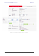
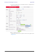
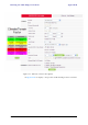

Table Of Contents
- Chapter 6
- Site Configuration
- Configuring the Site
- Viewing Air Interface Details
- Changing the Transmit Power
- Site Management: IP Address and VLAN
- Setting the Date and Time
- Ethernet Properties
- Displaying the Inventory
- Security Features
- Muting the alignment tone
- Setting External Alarm Inputs
- Managing Configuration Files
- Configuration with Telnet
- Site Configuration
- Chapter 7
- Appendix A
- Appendix B
- Appendix C
- Appendix D
- Appendix E
- Appendix F
- Appendix G
- Appendix H
- Appendix I
- Combo Configuration Tool
- What is the Combo Configuration Tool?
- Who may use the Combo Configuration Tool
- Caveat to the use of the Combo Configuration Tool
- Prerequisites to using the Combo Configuration Tool
- Operating the Combo Configuration Tool
- Before using the Combo Configuration Tool
- Using the Combo Configuration Tool
- If you receive an error message
- Combo Configuration Tool
- Appendix J
- Index

RADWIN 1000/2000/5000 User ManualVersion 2.6.50p E-1
Appendix E
Lightning Protection and
Grounding Guidelines
Meticulous implementation of the guidelines in this appendix will provide
best protection against electric shock and lightning.
The RADWIN 1000/2000/5000™ Lightning protection system consists of the
following components:
• Grounding for the antenna coax cable
• Grounding for each IDU and ODU
• External Primary Surge Suppressor units and grounding for the out-
door cable
• Internal ESD protection circuits over the Power/Telecom lines
Grounding for Antenna Cable
A Grounding Kit must be connected to the coax antenna cable and reliably
grounded as shown in Figure X. The grounding kit is an Andrew Type
223158-2 (www.andrew.com). See figure E-1 below.
Warning
100% protection is neither implied nor possible.
Note
This appendix is at best a guide. The actual degree of lightning protection
required depends on local conditions and regulations.