
User's Manual Part 1
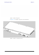
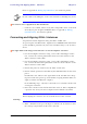
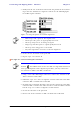
Table Of Contents
- Table of Contents
- List of Figures
- List of Tables
- Chapter 1
- Chapter 2
- Chapter 3
- Chapter 4
- Link Installation: The RADWIN Manager
- Installing theRADWIN Manager Application
- Starting the RADWIN Manager
- Login Errors
- Continuing without an IP Address
- Installing the Link: First steps
- Installing the Link: Overview
- Installing the Link: Step 1, Start the Wizard
- Installing the Link: Step 2, System Parameters
- Installing the Link: Step 3, Channel Settings
- Installing the Link: Step 4, Tx Power and Antenna Settings
- Installing the Link: Step 5, Services
- Installing the Link: Step 6, Installation Summary and Exit
- Link Installation: The RADWIN Manager
- Chapter 5
- Configuring the Link
- Link Configuration: Getting Started
- Configuring the Link: Overview
- Configuring the Link: Step 1, Start the Wizard
- Configuring the Link: Step 2, System Parameters
- Configuring the Link: Step 3, Channel Settings
- Configuring the Link: Step 4, Tx Power and Antenna Settings
- Configuring the Link: Step 5, Services
- Configuring the Link: Step 6, Configuration Summary and Exit
- Configuring the Link

Connecting the ODU to the IDU Chapter 3
RADWIN 1000/2000/5000 User ManualVersion 2.6.50p 3-12
Figure 3-11: DU-C ower connectors
The connectors are 3 pin in line female, with polarities (left to right) minus,
ground, plus. To avoid damage to the IDU, always use an AC/DC adapter
supplied by RADWIN.
Ensure that the IDUs at both sites are powered up.
Connecting the ODU to the IDU
The ODU-IDU cable conducts all the user traffic between the IDU and the
ODU, and also provides power to the ODU. The maximum length of the
ODU-IDU cable is 100m (328 ') in accordance with 10/100BaseT standards.
The ODU-IDU cable is supplied pre-assembled with RJ-45 connectors, at the
length specified when ordering, or as a cable drum with spare connectors. If
the ODU-IDU cable was not ordered, use an outdoor class, CAT-5e 24AWG
shielded cable. See appendix B for Wiring Specifications.
To connect the ODU to the IDU, route the cable from the ODU to the IDU,
secure the cable along its path and connect the cable to the ODU RJ-45
connector on the IDU (see item B in figure 3-8 above).
Installing a Link using PoE Devices
The PoE device is a very simple unit having a power input connector and
two Ethernet ports. It is AC powered, and has a power LED.
To prepare a link using PoE devices:
1. To connect the ODU to the PoE device, route the cable from the ODU to
the PoE device, secure the cable along its path and connect the cable to
the P-LAN-OUT RJ-45 connector on the PoE device.
2. Connect it to AC power.
3. Repeat steps 1 to 2 for the second link.
Connecting User Equipment
To connect user equipment to the IDU:
• Connect user switch/router or any other compatible device to the IDU
panel RJ-45 ports designated LAN (see item C in figure 3-8 above).