
User's Manual Part 2
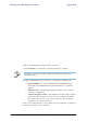

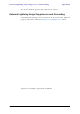
Table Of Contents
- Chapter 6
- Site Configuration
- Configuring the Site
- Viewing Air Interface Details
- Changing the Transmit Power
- Site Management: IP Address and VLAN
- Setting the Date and Time
- Ethernet Properties
- Displaying the Inventory
- Security Features
- Muting the alignment tone
- Setting External Alarm Inputs
- Managing Configuration Files
- Configuration with Telnet
- Site Configuration
- Chapter 7
- Appendix A
- Appendix B
- Appendix C
- Appendix D
- Appendix E
- Appendix F
- Appendix G
- Appendix H
- Appendix I
- Combo Configuration Tool
- What is the Combo Configuration Tool?
- Who may use the Combo Configuration Tool
- Caveat to the use of the Combo Configuration Tool
- Prerequisites to using the Combo Configuration Tool
- Operating the Combo Configuration Tool
- Before using the Combo Configuration Tool
- Using the Combo Configuration Tool
- If you receive an error message
- Combo Configuration Tool
- Appendix J
- Index

Grounding for Indoor/Outdoor Units Appendix E
RADWIN 1000/2000/5000 User ManualVersion 2.6.50p1 E-2
Figure E-1: Grounding antenna cables
Grounding for Indoor/Outdoor Units
ODU Grounding
RADWIN 1000/2000/5000™ uses a Shielded CAT-5e cable to interconnect
the Outdoor (ODU) and Indoor (IDU) units.
However, this shielding does not provide a good Lightning Discharge path,
since it can not tolerate the high Lightning Current surges.
To provide an alternate Lightning Discharge path, the ODU and antenna
grounding posts should be connected to ground point by a 10 AWG short
copper wire.
The device should be permanently connected to ground.
IDU Grounding
The IDUs grounding post should be connected to the internal ground point,
using a grounding wire of at least 10 AWG. The grounding wire should be
connected to a grounding rod or the building grounding system.