
User's Manual Part 2


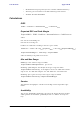
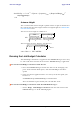

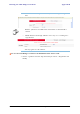
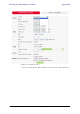
Table Of Contents
- Chapter 6
- Site Configuration
- Configuring the Site
- Viewing Air Interface Details
- Changing the Transmit Power
- Site Management: IP Address and VLAN
- Setting the Date and Time
- Ethernet Properties
- Displaying the Inventory
- Security Features
- Muting the alignment tone
- Setting External Alarm Inputs
- Managing Configuration Files
- Configuration with Telnet
- Site Configuration
- Chapter 7
- Appendix A
- Appendix B
- Appendix C
- Appendix D
- Appendix E
- Appendix F
- Appendix G
- Appendix H
- Appendix I
- Combo Configuration Tool
- What is the Combo Configuration Tool?
- Who may use the Combo Configuration Tool
- Caveat to the use of the Combo Configuration Tool
- Prerequisites to using the Combo Configuration Tool
- Operating the Combo Configuration Tool
- Before using the Combo Configuration Tool
- Using the Combo Configuration Tool
- If you receive an error message
- Combo Configuration Tool
- Appendix J
- Index

Running the Link Budget Calculator Appendix D
RADWIN 1000/2000/5000 User ManualVersion 2.6.50p1 D-8
Figure D-4: Rate selector
The Rate shown, defines the air-interface rate in Mbps. The system
operates in TDD mode and has the overhead of the air-interface pro-
toco.l Thus, the Ethernet actual throughput is provided by the Ethernet
Rate.
The Fade margin is the minimum required for LOS conditions. For
degraded link conditions, a larger Fade margin should be used.
The EIRP is given in dBm and Watts.
3. If the required range between the two link sites is known, you may enter
it directly. Alternatively, you may enter the latitude and longitude of each
site in the link, in which case the distance between them will be calcu-
lated and displayed.
Note
For a given air-rate, Ethernet throughput will decrease with increasing range
due to propagation delay.