
User's Manual Part 2


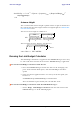

Table Of Contents
- Chapter 6
- Site Configuration
- Configuring the Site
- Viewing Air Interface Details
- Changing the Transmit Power
- Site Management: IP Address and VLAN
- Setting the Date and Time
- Ethernet Properties
- Displaying the Inventory
- Security Features
- Muting the alignment tone
- Setting External Alarm Inputs
- Managing Configuration Files
- Configuration with Telnet
- Site Configuration
- Chapter 7
- Appendix A
- Appendix B
- Appendix C
- Appendix D
- Appendix E
- Appendix F
- Appendix G
- Appendix H
- Appendix I
- Combo Configuration Tool
- What is the Combo Configuration Tool?
- Who may use the Combo Configuration Tool
- Caveat to the use of the Combo Configuration Tool
- Prerequisites to using the Combo Configuration Tool
- Operating the Combo Configuration Tool
- Before using the Combo Configuration Tool
- Using the Combo Configuration Tool
- If you receive an error message
- Combo Configuration Tool
- Appendix J
- Index

Calculations Appendix D
RADWIN 1000/2000/5000 User ManualVersion 2.6.50p1 D-2
• Maximum linear input power (used to calculate minimum distance)
• Antenna gain and cable loss for ODU with integrated antenna
• Available Channel Bandwidths
Calculations
EIRP
Expected RSS and Fade Margin
where:
Site A is the transmitting site
Site B is the receiving site
PathLoss is calculated according to the free space model,
where Sensitivity is dependent on air-rate.
Min and Max Range
MinRange is the shortest range for which
per air-rate.
MaxRange (with Adaptive checked) is the largest range for which
, at the highest air-rate for which this relation-
ship is true. In a link with adaptive rate this will be the actual behavior.
MaxRange (for a given air-rate) is the largest range for which
.
Service
The Ethernet throughput is calculated according to internal product algo-
rithms.
Availability
The Service Availability calculation is based on the Vigants Barnett method
which predicts the downtime probability based on a climate factor (C fac-
tor).
EIRP TxPower AntennaGain
SiteA
CableLoss
SiteA
–+=
ExpectedRSS EIRP PathLoss AntennaGain
SiteB
CableLoss
SiteB
–+–=
PathLoss 32.45 20 frequency
MHz
20 RequiredRange
Km
10
log+
10
log+=
ExpectedFadeM inarg Sensitivity ExpectedRSS–=
ExpectedRSS MaxInputPower
ExpectedRSS Sensitivity
ExpectedRSS Sensitivity RequiredFadeM inarg+