
User's Manual Part 2
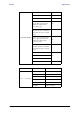
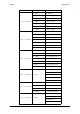
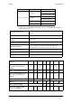
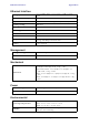
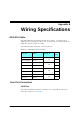

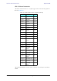
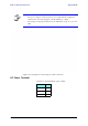
Table Of Contents
- Chapter 6
- Site Configuration
- Configuring the Site
- Viewing Air Interface Details
- Changing the Transmit Power
- Site Management: IP Address and VLAN
- Setting the Date and Time
- Ethernet Properties
- Displaying the Inventory
- Security Features
- Muting the alignment tone
- Setting External Alarm Inputs
- Managing Configuration Files
- Configuration with Telnet
- Site Configuration
- Chapter 7
- Appendix A
- Appendix B
- Appendix C
- Appendix D
- Appendix E
- Appendix F
- Appendix G
- Appendix H
- Appendix I
- Combo Configuration Tool
- What is the Combo Configuration Tool?
- Who may use the Combo Configuration Tool
- Caveat to the use of the Combo Configuration Tool
- Prerequisites to using the Combo Configuration Tool
- Operating the Combo Configuration Tool
- Before using the Combo Configuration Tool
- Using the Combo Configuration Tool
- If you receive an error message
- Combo Configuration Tool
- Appendix J
- Index

IDU-C Alarm Connector Appendix B
RADWIN 1000/2000/5000 User ManualVersion 2.6.50p1 B-3
IDU-C Alarm Connector
The IDU-C Alarm interface is a 25 pin D type female connector. Its pinout is
listed in table B-3.
The following diagram describes how to connect external input and output
alarms.
Table B-3: IDU-C Alarm Connector (Dry-Contact)
I/O Description Pin
Input 1 Positive 14
Input 1 Negative 15
Input 2 Positive 16
Input 2 Negative 17
Input 3 Positive 18
Input 3 Negative 19
Input 4 Positive 20
Input 4 Negative 21
Output 1 Normally Open 1
Output 1 Common 2
Output 1 Normally
Closed
3
Output 2 Normally Open 4
Output 2 Common 5
Output 2 Normally
Closed
6
Output 3 Normally Open 7
Output 3 Common 8
Output 3 Normally
Closed
9
Output 4 Normally Open 10
Output 4 Common 11
Output 4 Normally
Closed
12