
User's Manual Part 1
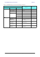
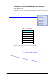
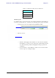
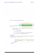
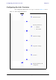
Table Of Contents
- Table of Contents
- List of Figures
- List of Tables
- Chapter 1
- Chapter 2
- Chapter 3
- Chapter 4
- Link Installation: The RADWIN Manager
- Installing theRADWIN Manager Application
- Starting the RADWIN Manager
- Login Errors
- Continuing without an IP Address
- Installing the Link: First steps
- Installing the Link: Overview
- Installing the Link: Step 1, Start the Wizard
- Installing the Link: Step 2, System Parameters
- Installing the Link: Step 3, Channel Settings
- Installing the Link: Step 4, Tx Power and Antenna Settings
- Installing the Link: Step 5, Services
- Installing the Link: Step 6, Installation Summary and Exit
- Link Installation: The RADWIN Manager
- Chapter 5
- Configuring the Link
- Link Configuration: Getting Started
- Configuring the Link: Overview
- Configuring the Link: Step 1, Start the Wizard
- Configuring the Link: Step 2, System Parameters
- Configuring the Link: Step 3, Channel Settings
- Configuring the Link: Step 4, Tx Power and Antenna Settings
- Configuring the Link: Step 5, Services
- Configuring the Link: Step 6, Configuration Summary and Exit
- Configuring the Link

Elements of the RADWIN Manager Main Window Chapter 5
RADWIN 1000/2000/5000 User ManualVersion 2.6.50p1 5-7
Monitor pane
he monitor pane, is the main source of real time information about link per-
formance at both link sites. It includes the following panes (top to bottom):
• Radio Interface, Received Signal Strength (RSS) in dBm
• Ethernet Service:
• Ethernet Throughput: The numbers are the current calculated
throughputs at each site. The colored bars (with numbers) indi-
cate the maximum possible throughput having regard for air
conditions.
• Rx and Tx Rates: Actual Ethernet traffic received and transmit-
ted rates per site, in Mbps of Fbps.
Table 5-4: Link site details, Site A and Site B
Item
IP Address
Subnet Mask
Trap Desalination