
User's Manual Part 1
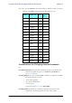
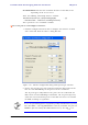
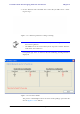
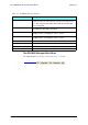
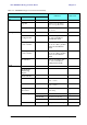
Table Of Contents
- Table of Contents
- List of Figures
- List of Tables
- Chapter 1
- Chapter 2
- Chapter 3
- Chapter 4
- Link Installation: The RADWIN Manager
- Installing theRADWIN Manager Application
- Starting the RADWIN Manager
- Login Errors
- Continuing without an IP Address
- Installing the Link: First steps
- Installing the Link: Overview
- Installing the Link: Step 1, Start the Wizard
- Installing the Link: Step 2, System Parameters
- Installing the Link: Step 3, Channel Settings
- Installing the Link: Step 4, Tx Power and Antenna Settings
- Installing the Link: Step 5, Services
- Installing the Link: Step 6, Installation Summary and Exit
- Link Installation: The RADWIN Manager
- Chapter 5
- Configuring the Link
- Link Configuration: Getting Started
- Configuring the Link: Overview
- Configuring the Link: Step 1, Start the Wizard
- Configuring the Link: Step 2, System Parameters
- Configuring the Link: Step 3, Channel Settings
- Configuring the Link: Step 4, Tx Power and Antenna Settings
- Configuring the Link: Step 5, Services
- Configuring the Link: Step 6, Configuration Summary and Exit
- Configuring the Link

The RADWIN Manager Toolbar Chapter 5
RADWIN 1000/2000/5000 User ManualVersion 2.6.50p1 5-2
.
Figure 5-1: Main window, Wireless Link is Active
Before starting a configuration session, make sure that a communication
link exists between the two sides of the link.
The Link Status indication bar must be green. In the Link Status panel, the
Status field should show Link Active in green.
The main window of the RADWIN Manager contains a large amount of
information about the link. Before proceeding to details of link configuration
we set out the meaning of each item in the main window.
The RADWIN Manager Toolbar
In configuration mode, the RADWIN Manager toolbar contains the following
buttons: