
User's Manual Part 1
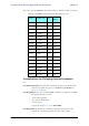
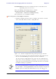
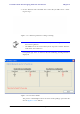
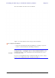
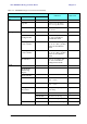
Table Of Contents
- Table of Contents
- List of Figures
- List of Tables
- Chapter 1
- Chapter 2
- Chapter 3
- Chapter 4
- Link Installation: The RADWIN Manager
- Installing theRADWIN Manager Application
- Starting the RADWIN Manager
- Login Errors
- Continuing without an IP Address
- Installing the Link: First steps
- Installing the Link: Overview
- Installing the Link: Step 1, Start the Wizard
- Installing the Link: Step 2, System Parameters
- Installing the Link: Step 3, Channel Settings
- Installing the Link: Step 4, Tx Power and Antenna Settings
- Installing the Link: Step 5, Services
- Installing the Link: Step 6, Installation Summary and Exit
- Link Installation: The RADWIN Manager
- Chapter 5
- Configuring the Link
- Link Configuration: Getting Started
- Configuring the Link: Overview
- Configuring the Link: Step 1, Start the Wizard
- Configuring the Link: Step 2, System Parameters
- Configuring the Link: Step 3, Channel Settings
- Configuring the Link: Step 4, Tx Power and Antenna Settings
- Configuring the Link: Step 5, Services
- Configuring the Link: Step 6, Configuration Summary and Exit
- Configuring the Link

Considerations for Changing Antenna Parameters Chapter 4
RADWIN 1000/2000/5000 User ManualVersion 2.6.50p1 4-24
3. Set the Antenna Gain and Cable Loss. If do this you will receive a warn-
ing message:
Figure 4-17: Antenna parameters change warning
If inequality (*) above is violated, then the following warning window is
displayed:
Figure 4-18: Tx Power Limits
The precise relationship between the items in inequality (*) and the win-
dow of figure 4-16 is follows:
Note
• The Max EIRP level will be automatically set according to the selected
band and regulation.
• The EIRP level is the sum of the System Tx power and the Antenna
Gain minus the Cable Loss.