
User's Manual Part 1
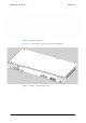
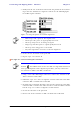
Table Of Contents
- Table of Contents
- List of Figures
- List of Tables
- Chapter 1
- Chapter 2
- Chapter 3
- Chapter 4
- Link Installation: The RADWIN Manager
- Installing theRADWIN Manager Application
- Starting the RADWIN Manager
- Login Errors
- Continuing without an IP Address
- Installing the Link: First steps
- Installing the Link: Overview
- Installing the Link: Step 1, Start the Wizard
- Installing the Link: Step 2, System Parameters
- Installing the Link: Step 3, Channel Settings
- Installing the Link: Step 4, Tx Power and Antenna Settings
- Installing the Link: Step 5, Services
- Installing the Link: Step 6, Installation Summary and Exit
- Link Installation: The RADWIN Manager
- Chapter 5
- Configuring the Link
- Link Configuration: Getting Started
- Configuring the Link: Overview
- Configuring the Link: Step 1, Start the Wizard
- Configuring the Link: Step 2, System Parameters
- Configuring the Link: Step 3, Channel Settings
- Configuring the Link: Step 4, Tx Power and Antenna Settings
- Configuring the Link: Step 5, Services
- Configuring the Link: Step 6, Configuration Summary and Exit
- Configuring the Link

Connecting and Aligning ODUs / Antennas Chapter 3
RADWIN 1000/2000/5000 User ManualVersion 2.6.50p1 3-13
Refer to appendix B, Wiring Specifications, for connector pinouts.
To connect user equipment to the PoE device:
• Connect a user switch, router or any other compatible device to the PoE
device RJ-45 port designated LAN-IN. Refer to appendix B, Wiring
Specifications, for connector pinouts.
Connecting and Aligning ODUs / Antennas
You perform antenna alignment using the ODU's audible tone.
To speed up the installation time, alignment of a RADWIN 1000/2000/5000
system should be performed by two teams simultaneously, at site A and at
site B.
To align ODUs with integrated antennas or external bipolar antennas:
1. For external bipolar antennas: Using a coax cable with N-Type connec-
tors, connect the vertical polarization connector of the antenna to the
ANT 1 connector of the ODU.
2. For external bipolar antennas: Using a coax cable with N-Type connec-
tors, connect the horizontal polarization connector of the antenna to the
ANT 2 connector of the ODU.
3. Ensure that power is connected to the IDUs at both sites.
4. Ensure normal operation of the IDUs by the LED indications on the front
panel.
Provided that site A detects the signal from site B, the ODU starts beep-
ing 20 seconds after power up, and continues beeping until the ODUs are
aligned, and the installation is complete.
In the following steps, “antenna” refers both to an external antenna and
an integrated antenna.
5. Direct the antenna of site B in the direction of site A. This is simplified if
a previous site survey has been completed and azimuths are known.
6. Make a horizontal sweep of 180 degrees with the site A antenna so that
the strongest signal from site B can be detected.
Note
Do not connect two LAN ports to the same network, or flooding may occur.
Warning
When aligning the antennas, do not stand in front of a live antenna.