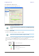
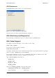
Configuring the GSU Chapter 11 Site Configuration: GPS Sync Unit This window is the main GSU configuration tool: Figure 11-8: Site Configuration: GPS Sync Unit Note The 1000 and 2000 labels refer to WinLink 1000 and RADWIN 2000 radios, respectively. The actual annotation seen may vary, but the intention should be clear. 1. Setting the RFP for HSS The GSU is automatically configured as HSS Master (HSM). Ensure that no other collocated ODU is configured as HSM.
Configuring the GSU Chapter 11 There is a further restriction: If there are two distributed sites transmitting to each other, they must both use the same RFP. This requirement, together with use of shifted transmission phase (item 3 below), ensures that communicating distributed sites to not interfere with each other by transmitting simultaneously. Two GSU managed sites transmitting with shifted transmission phase and using the same RFP, transmit one half a RFD apart (see Figure 11-3 above). 2.
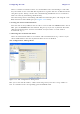
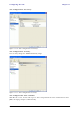
Configuring the GSU Chapter 11 Site Configuration: Inventory Figure 11-10: Site Configuration: Inventory Site Configuration: Security You can only change the SNMP Community stings: Figure 11-11: Site Configuration: Security Site Configuration: Date and Time ODU Recent events, alarms and traps are time-stamped from the time method chosen here (NTP, managing computer, ODU default). RADWIN 2000 User Manual Release 2.5.
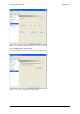
Configuring the GSU Chapter 11 Figure 11-12: Setting the date and time for trap reporting Site Configuration: Operations The only available action here is Restore System Defaults: Figure 11-13: Site Configuration: Operations RADWIN 2000 User Manual Release 2.5.
GSU Preferences Chapter 11 GSU Preferences The Preferences window adds a new tab for the GSU: Figure 11-14: Site Configuration: Operations You may chose the units for latitude/longitude coordinates. GSU Monitoring and Diagnostics The monitoring and diagnostic reports are similar to those of WinLink 1000. GSU Telnet Support To configure the GSU with Telnet, start a Telnet session, using telnet . For example, if you run Telnet as follows, telnet 192.168.222.
Software Update for GSUs Chapter 11 Current GPS latitude 51.500000 Current GPS N\S Indicator N Current GPS longitude 0.000000 Current GPS E\W Indicator E Current GPS number of satellites 09 Current GPS altitude 84.0 Command "display gpsinfo" finished OK. The three additional set commands are set rfp (2-6) set ratio set tx_phase Software Update for GSUs All GSUs in a distributed site can be updated simultaneously.
RADWIN 2000 Broadband Wireless Transmission System USER MANUAL RELEASE 2.5.40 Part 3: Advanced Installation UM 2000-2540/02.
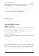
Chapter 12 Monitored Hot Standby Installation Procedure What is a RADWIN Monitored Hot Standby The RADWIN Monitored Hot Standby (MHS a.k.a 1+1) is a duplicated link set up as a primary link and a secondary link in hot standby mode as shown in Figure 12-1 below. Figure 12-1: RADWIN Monitored Hot Standby RADWIN 2000 User Manual Release 2.5.
What RADWIN MHS provides Chapter 12 RADWIN MHS provides redundancy and backup to TDM services. It is designed to provide high reliability high-capacity Point-to-Point links.
Purpose of this Chapter Chapter 12 Purpose of this Chapter This chapter is an installation and maintenance guide for RADWIN MHS. It applies to all RADWIN radio products able to support the Monitored Hot Standby operational mode. Who Should Read this This chapter is intended for persons responsible for the installation and maintenance of RADWIN MHS.
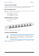
Installing a RADWIN MHS Chapter 12 Figure 12-3: How to connect the IDUs to the Patch Panel • • Note With RADWIN 2000 links you can protect up to 16 TDM ports. To protect more than eight TDM ports use two Patch Panels at each site. Ethernet services are carried independently by primary and secondary links. Each link carries different Ethernet traffic. MHS does not protect Ethernet traffic. In what follows, it will be assumed that – 1. We will depart from our usual Site A / Site B conventions.
Installing a RADWIN MHS Chapter 12 6. Connect the MHS cables at Sites A and B as shown in Figure 12-1 and Figure 123 above. 7. Run the Configuration Wizard for Primary Link. Activate TDM services in the usual way. Navigate to the Hot Standby tab, in the Services Configuration panel: Figure 12-4: Services Configuration Panel: Hot Standby mode selection Check the Primary button to configure Primary Link as the primary link. 8. Complete the Wizard, and then move to Secondary Link. 9.
Installing a RADWIN MHS Chapter 12 Figure 12-5: The primary link under normal operation RADWIN 2000 User Manual Release 2.5.
Installing a RADWIN MHS Chapter 12 Figure 12-6: The secondary link under normal operation To see what happens following a cut-over from the primary link to the secondary link, you need to have running two copies of the RADWIN Manager – one logged into the primary link, and one logged into the secondary link. Here then, is the situation after a cut-over to the secondary link: For the primary link, the following window will appear for a few seconds: RADWIN 2000 User Manual Release 2.5.
Installing a RADWIN MHS Chapter 12 Figure 12-7: Primary link a few seconds before regular No-Link display It will then revert to the standard No-Link-available window. On the secondary link Manager window, you will see a window like this: RADWIN 2000 User Manual Release 2.5.
Maintaining a RADWIN MHS Link Chapter 12 Figure 12-8: Secondary Link operating as the Hot Standby link Notice that the active link notice is highlighted in red, so that there is no mistaking which link is operational. Maintaining a RADWIN MHS Link IDU Replacement There are two situations, which must be treated differently. Situation 1: To replace either of the IDUs at Site 1.4 or the IDU at Site 2.2, nothing special is required. Simply disconnect the IDU to be replaced – and replace it with a new one.
ODU Replacement Chapter 12 2. Run the Configuration manager on the secondary link, and in the Hot Standby panel of Figure 12-4 above, check the Disabled button. 3. Replace the Site 1.2 IDU without connecting it to the ODU (to prevent transmission by the primary link with the undefined IDU). 4. Reconnect the MHS cable between the IDUs at Site 1.2. 5.
Switching from Primary Link to Secondary Link Chapter 12 • Loss of the primary air interface due to failure of the receiver to acquire expected E1/ T1 data during a period of 24ms • The Primary equipment (either ODU or IDU, local or remote) is powered off Following the switch from the primary to the secondary link, the primary and secondary link Manager main windows should look like this: Figure 12-9: Primary link after the switch over to secondary link (After a few seconds the display moves to No-Li
Switching back from the Secondary to the Primary Link Chapter 12 Figure 12-10: Secondary link operating after the switch over to secondary. (After a few moments the TDM icons become green.) Switching back from the Secondary to the Primary Link Switching back from the secondary link to the primary link will occur after the primary link has become and remains fully functional for a continuous period of at least one second.
Switching back from the Secondary to the Primary Link Chapter 12 Figure 12-11: Primary link operating after the switch back from secondary RADWIN 2000 User Manual Release 2.5.
System Operation description Chapter 12 Figure 12-12: Secondary Link operating after the switch back to Primary System Operation description • Normal operation TDM services are carried by the primary link • The secondary link (equipment and air interface) is operating but not carrying user traffic • TDM ports on the secondary IDUs are tri-state • Switching to secondary will occur in the following cases: • • Switching to backup • Loss of the primary air interface due to sync loss Loss of the prim
Chapter 13 The RADWIN Ethernet Ring Scope The description of RADWIN Ethernet Ring in this Chapter is completely generic: Both WinLink 1000 and RADWIN 2000 links may participate in an Ethernet ring. Caution VLAN IDs are used by RADWIN products in three separate contexts: Management VLAN, Traffic VLAN and Ethernet Ring. It is recommended that you use different VLAN IDs for each context. What is an Ethernet Ring An Ethernet ring consists of several nodes connected by hops (links).
RADWIN Ethernet Ring • Chapter 13 Ring Protection Message (RPM) - control message used to monitor and control the ring. Note RPM messages are broadcast, so it is essential (to prevent flooding) to associate the RPL and member Ring LInks with a VLAN ID. This requires in turn, that equipment used in the ring either supports VLAN or can transparently pass through VLAN tagged packets. RADWIN Ethernet Ring The following figure describes the RPL behavior during a ring failure and recovery cycle.
RADWIN Ethernet Ring Chapter 13 The steps below follow the numbering in Figure 13-1: 1. Normal operation Ethernet traffic runs in the ring, but does not pass through the RPL, which is blocked. The RPL does however, broadcast RPM packets through the ring. 2. Ring Link down, RPL notified The RPL detects a link-down condition by the non-arrival of an RPM packet. It remains blocked for the Minimum time for failure detection which is configurable using the RADWIN Manager (see page 13-9). 3.
Ethernet Ring Topologies Supported by RADWIN Chapter 13 Ethernet Ring Topologies Supported by RADWIN The following ring topologies are supported: Table 13-1: Topologies supported by RADWIN Ethernet Ring The ring is not connected to other rings Stand-alone ring One of the nodes is connected to another network / ring: Single-homed ring Two adjacent nodes are connected through a non-RADWIN link (e.g.
Ethernet Ring Topologies Supported by RADWIN Chapter 13 Table 13-1: Topologies supported by RADWIN Ethernet Ring (Continued) Some of the hops are connected through non-RADWIN links: Mixed ring Some of the hops are connected through RADWIN links with PoE devices, not supporting ring functionality: Repeater sites RADWIN rings with shared hops.
Protection Switching Chapter 13 Protection Switching Protection switching occurs upon failure in the ring. The Ethernet service restoration time depends on the number of hops in the ring. With four hops the Ethernet service is restored in less than 50 ms. In single and dual homed topologies the service restoration may take longer due to the aging time of the external switches. Switches that are immediately aware of routing changes reduce the restoration time.
Using RADWIN Manager to Set up a Ring Chapter 13 The equipment in a 1+1 Ethernet installation is as follows: Figure 13-3: 1+1 Ethernet Figure 13-4: Using IDU-C or IDU-E with PoEs for the RPL Notice that link content drops from four PoEs plus two switches to two PoEs and two IDU-Cs or IDU-Es. Using RADWIN Manager to Set up a Ring Creating a Ring using RADWIN Manager requires two stages: 6. Set up each participating link separately, in the usual way 7.
Using RADWIN Manager to Set up a Ring Chapter 13 To integrate a link into an Ethernet Ring: 1. Using either the Installation or Configuration wizards, navigate to the Services window and chose the Ring tab. Figure 13-5: Services window with Ring selected 2. Click Configure. The Ring definition window is displayed. The default is Independent Link and is used when the link is not part of any Ring. Figure 13-6: Ring Options 3.
Using RADWIN Manager to Set up a Ring Chapter 13 Figure 13-7: Configuring Ring LAN VIDs 4. To configure the link as RPL, click Ring Protection Link (RPL) and enter its Ring VID. Figure 13-8: Configuring RPL VIDs 5. Enter the minimum times for failure detection and recovery. For dual-homed configurations, where part of the ring goes through the core, if a core segment fails, the core should be allowed to recover before the RPL enters Protection State.
Using RADWIN Manager to Set up a Ring Chapter 13 The RPL will be clearly indicated in the RADWIN Manager. In the Link status area on the top left, you will see an Ethernet (Blocked) notice: A Link-Idle message is displayed on the Ethernet Services Bar: When the RPL cuts in as a result of a failure, the “Ethernet (Blocked)” notice disappears.
Chapter 14 VLAN Functionality with RADWIN 2000 VLAN Tagging - Overview VLAN Terminology Both the technical literature and the RADWIN Manager use the terms VLAN ID and VID interchangeably to denote a VLAN identification number. VLAN Background Information on the WEB The standards defining VLAN Tagging are IEEE_802.1Q and extensions. For general background about VLAN see http://en.wikipedia.org/wiki/Virtual_LAN. Background information about Double Tagging also known as QinQ may be found here: http://en.
QinQ (Double Tagging) for Service Providers Chapter 14 IEEE 802.1Q is used as the encapsulation protocol to implement this mechanism over Ethernet networks. QinQ (Double Tagging) for Service Providers QinQ is useful for Service Providers, allowing them to use VLANs internally in their “transport network” while mixing Ethernet traffic from clients that are already VLAN-tagged.
Port Functionality Chapter 14 Ingress Direction Table 14-1: Port settings - Ingress direction Transparent The port ‘does nothing’ with regard to VLANs - inbound frames are left untouched. Frames entering the port without VLAN or QinQ tagging are tagged with VLAN ID and Prioritya, which are pre-configured by the user. Frames which are already tagged at ingress are not modified. Tag a. Priority Code Point (PCP) which refers to the IEEE 802.1p priority.
Port Functionality Chapter 14 Table 14-2: Port settings - Egress direction (Continued) Untags only frames tagged with one of the user defined VIDs. You can define up to eight VIDs per port. Other frames are not modified. Untag selected VIDs This setting allows for mutual filtering of multiple ingress tags not relevant at the egress end: Filtered VLAN IDs at egress RADWIN 2000 User Manual Release 2.5.
VLAN Availability Chapter 14 Table 14-2: Port settings - Egress direction (Continued) With Provider tagging, the system double-tags egress frames towards the provider’s network. All frames are tagged QinQ with a VLAN ID, which is configured by the service provider (Provider VLAN ID). Provider tagging With this setting, ingress frames which are not tagged with the configured Provider VLAN ID are blocked (filtered). Note: Each port can be configured independently to a tagging mode.
Management Traffic and Ethernet Service Separation Chapter 14 Management Traffic and Ethernet Service Separation You can define a VLAN ID for management traffic separation. You should configure the system to prevent conflicts as detailed below.
VLAN Tagging for Ethernet Service: Configuration Chapter 14 Figure 14-3: VLAN tag settings If you are using a new style IDU-E, the SFP row will not appear. Note The choices for Ingress Mode are - Figure 14-4: VLAN: Ingress modes The two choices correspond respectively to the two rows of Table 14-1. Choosing Tag causes the VLAN ID and VLAN Priority fields to become available: RADWIN 2000 User Manual Release 2.5.
VLAN Tagging for Ethernet Service: Configuration Chapter 14 Figure 14-5: VLAN: Ingress mode - setting VLAN ID and Priority Note Throughout this chapter, all VLAN IDs must be between 1 and 4094, inclusive. All VLAN priorities must be between 0 and 6, inclusive. The values entered are range-checked. If for example, you enter a VLAN ID of 4095, then 4094 will be reflected back.
VLAN Tagging for Ethernet Service: Configuration Chapter 14 There is of course only one Provider VLAN ID. It is most likely yours, as the Provider! Filtered VLAN IDs enables you to filter and block only frames tagged with one of the user defined VIDs. You can define up to eight VIDs per port. Other frames are not modified and are forwarded transparently. When you are finished, remember to click OK (Figure 14-3) to save your entries. RADWIN 2000 User Manual Release 2.5.
Chapter 15 Software Upgrade What is the Software Upgrade Utility? The RADWIN Manager provides a Software Upgrade Utility (SWU) to upgrade the software (firmware) of installed ODUs in a network. The update files may be located anywhere accessible by the operator.
Upgrading an Installed Link Chapter 15 Figure 15-1: Software Upgrade Utility - Main window The default sites shown in the Software Upgrade list panel belong to the currently link. The list may be empty if you are running the RADWIN Manager “offline”. Warning What follows about adding sites manually or from a list file, assumes that all sites to be upgraded are of the same type - either WinLink 1000 or RADWIN 2000. but not both. This will not work with a mixed list. 2.
Upgrading an Installed Link Chapter 15 Enter the IP address of the site, the Community strings (Default: public and netman, respectively) and then click OK. The site will appear in the Software Upgrade list box. For example if we add the site at IP address 192.168.2.101, the SWU main window of Figure 15-1 looks like this: Figure 15-4: Single site added for upgrade The list can be cleared using the Clear All button.
Upgrading an Installed Link Chapter 15 5. To back up your existing system, check Backup device software check-box. Then click the button for a standard file dialog. The default location is the My Documents directory on the managing computer or the last backup directory you used. Note The backup here is the same as that in page 8-32, and serves the same purpose. It provides a fallback if the upgrade proves problematic. 6. In addition to the previous step, you may opt to perform a delayed upgrade.
Software Update for GSUs Chapter 15 If one or both sites fail to update, a warning notice will be displayed. Caution If one site of a link updates but the other fails, you should correct the problem and update the second site as soon as possible. If you do not, following the next reset of the updated site, you could experience a link software mismatch which may affect service. See page 9-3 for details. Software Update for GSUs All GSUs in a distributed site can be updated simultaneously.
Chapter 16 FCC/IC DFS Installation Procedure FCC/IC 5.4/5.3 GHz Links: Background The FCC/IC regulation for 5.4/5.3 GHz allows unlicensed wireless data equipment, provided that it does not interrupt radar services. If radar activity is detected, the equipment must automatically change frequency channel. This feature is termed Dynamic Frequency Selection (DFS). According to the standard, a channel with active radar is prohibited from use for 30 minutes.
FCC/IC 5.4/5.3 GHz Link Activation Chapter 16 Figure 16-1: Activating an ODU - Inactive link When the Manager Main Screen is displayed it appears with the Link Status label red and showing Inactive. 4. Click Site:Location | Air Interface for the logged in site. 5. The Air Interface dialog box opens: Figure 16-2: Air Interface dialog box 6. Enter the Link ID and note it for use with the second site of the link. 7. Check the Master radio button. RADWIN 2000 User Manual Release 2.5.
FCC/IC 5.4/5.3 GHz Link Activation Chapter 16 8. Click OK. The following window appears: Figure 16-3: The local ODU after activation - Probing Notice that the Link ID is shown in the Link details pane (circled). 9. Repeat the above procedure for the remote ODU, ensuring that in the Air Interface window, that you enter exactly the same Link ID, but this time that you check the Slave radio button. If both ODUs are powered up, after a minute or so a link will be established.
FCC/IC 5.4/5.3 GHz Link Configuration Chapter 16 Figure 16-4: Both sites activated and awaiting configuration FCC/IC 5.4/5.3 GHz Link Configuration The Configuration procedure may be carried out from either site using the Configuration wizard as shown in Chapter 7. Note Both sites in a FCC/IC 5.4/5.3 GHz Link must be configured identically. The only difference is in the Channel Settings window: RADWIN 2000 User Manual Release 2.5.
FCC/IC 5.4/5.3 GHz Link Configuration Chapter 16 Figure 16-5: Channel Select dialog box - ACS permanently enabled ACS cannot be disabled. Note Upon completion of the wizard, the Site configuration dialogs can be used in the usual way. Once operational, the RADWIN Manager window is the same as for other radio equipment models. Here is the RADWIN Manager main window upon completion of the wizard: RADWIN 2000 User Manual Release 2.5.
FCC/IC 5.4/5.3 GHz Link Configuration Chapter 16 Figure 16-6: FCC/IC 5.4/5.3 GHz operational RADWIN 2000 User Manual Release 2.5.
RADWIN 2000 Broadband Wireless Transmission System USER MANUAL RELEASE 2.5.40 Part 4: Field Installation Topics UM 2000-2540/02.
Chapter 17 Pole and Wall Installation ODU Mounting Kit Contents Table 17-1: Bill of Materials: ODU mounting kit Item Qty Large Clamp (see Figure 17-1) 1 Small Clamp (see Figure 17-2) 1 Arm (see Figure 17-3) 1 Screw hex head M8x40 4 Screw hex head M8x70 2 Washer flat M8 4 Washer spring M8 3 M8 Nuts 2 Figure 17-1: Large Clamp Figure 17-2: Small Clamp RADWIN 2000 User Manual Release 2.5.
Mounting an ODU on a Pole Chapter 17 Mounting an ODU on a Pole Figure 17-4: Mounting on a pole RADWIN 2000 User Manual Release 2.5.
Mounting an ODU on a Wall Chapter 17 Mounting an ODU on a Wall Figure 17-5: Mounting on a Wall RADWIN 2000 User Manual Release 2.5.
Mounting an External Antenna Chapter 17 Mounting an External Antenna Optional external antennas can be mounted on a pole. The external mounting kit varies according to the specific antenna model. Mounting a Connectorized ODU Horizontally What follows applies to both WinLink 1000 and RADWIN 2000 with obvious differences. An ODU may be mounted horizontally as shown in Figure 17-6. To mount an ODU horizontally, observe the following cautions: 1.
Chapter 18 Lightning Protection and Grounding Guidelines Meticulous implementation of the guidelines in this chapter will provide best protection against electric shock and lightning. 100% protection is neither implied nor possible. Warning Note This chapter is at best a guide. The actual degree of lightning protection required depends on local conditions and regulations.
Grounding for Indoor/Outdoor Units Chapter 18 Figure 18-1: Grounding antenna cables Grounding for Indoor/Outdoor Units ODU Grounding RADWIN Lightning Protection System uses a Shielded CAT-5e cable to interconnect the Outdoor (ODU) and Indoor (IDU) units. However, this shielding does not provide a good lightning discharge path, since it can not tolerate the high Lightning Current surges.
IDU Grounding Chapter 18 IDU Grounding The IDU’s grounding post should be connected to the internal ground point, using a grounding wire of at least 10 AWG. The grounding wire should be connected to a grounding rod or the building grounding system. The device should be permanently connected to ground.
External Lightning Surge Suppressors and Grounding Chapter 18 Figure 18-2: Grounding a typical pole installation RADWIN 2000 User Manual Release 2.5.
External Lightning Surge Suppressors and Grounding Chapter 18 Figure 18-3: Grounding a typical wall installation The next figure shows a close-up of the rear of grounded ODU: Figure 18-4: ODU Surge Suppressor and grounding RADWIN 2000 User Manual Release 2.5.
External Lightning Surge Suppressors and Grounding Chapter 18 The Transtector protection circuits shown in Figure 18-5 below, utilize silicon avalanche diode technology. The unit consists of an outdoor rated NEMA 3R type enclosure with easy mounting flanges, ground stud attachment and easy wiring. The ALPU-POE features RJ-45 protection circuits for the ODU-IDU data pairs (pins 1,2 & 3,6) and DC power (pins 4,5 & 6,7 with the pairs bonded). The unit is designed to be wall mounted.
External Lightning Surge Suppressors and Grounding Chapter 18 A second Surge Arrestor Unit should be mounted at the building entry point and must be grounded, as shown in Figure 18-3 above. To mount the lightning protection at the building entry point: 1. Mount the device outside the building, located as near as possible to the entrance of the CAT-5e ODU-IDU cable.
Internal ESD Protection circuits Chapter 18 Internal ESD Protection circuits RADWIN equipment is designed to meet the ETSI/FCC/Aus/NZ/CSA EMC and Safety requirements. To fulfill these requirements, the system's Telecom lines at the ODU/IDU are Transformer-isolated and include internal ESD (Electro-Static-Discharge) Protection circuits. RADWIN 2000 User Manual Release 2.5.
Chapter 19 Preloading an ODU with an IP Address Why this is Needed? All ODUs supplied by RADWIN come pre-configured with an IP address of 10.0.0.120. For use in a network, the ODUs must be configured with suitable static IP addresses. The method for doing this under office conditions is set out in Chapter 5.
The procedure Chapter 19 The procedure Note The following procedure is generic to all RADWIN radio products. What you see on your running RADWIN Manager may differ in some details from the screen captures used to illustrate this chapter. To Preolad an ODU with an IP address: 1. Using the IDU-ODU cable, connect the PoE device to the ODU, ensuring that the cable is plugged into the PoE port marked P-LAN-OUT. 2. For connectorized ODUs, screw the RF terminators into the two antenna ports.
The procedure Chapter 19 Figure 19-2: Opening RADWIN Manager window prior to installation 8. Click the un-grayed Site:Location button. The following dialog window appears: Figure 19-3: Configuration Dialog Box 9. Click the Management item in the left hand panel. The following window is presented: RADWIN 2000 User Manual Release 2.5.
The procedure Chapter 19 Figure 19-4: Management Addresses - Site Configuration dialog box 10. Enter the IP Address, Subnet Mask and Default Gateway as requested. For example, the ODU used here is to be configured as follows: Figure 19-5: ODU with IP Addressing configured 11. Click OK. You are asked to confirm the change: Figure 19-6: Confirmation of IP Address change RADWIN 2000 User Manual Release 2.5.
The procedure Chapter 19 12. Click Yes to accept the change. After about half a minute the changes will be registered in the ODU. On the left hand panel of the main window, you will see the new IP configuration for the ODU. Figure 19-7: Main Window after IP Address change Some additional things you may want to do now: • Note • Go to Site Installation | Air Interface. You can enter a Link ID and change the Installation Frequency and Channel Bandwidth.
Tip: How to Recover a Forgotten ODU IP Address Chapter 19 Tip: How to Recover a Forgotten ODU IP Address If you have an ODU with lost or forgotten IP address, use the above procedure to log on to it using Local Connection. The IP address will appear in the left hand status area: Figure 19-8: Existing IP address displayed after log-on with Local Connection RADWIN 2000 User Manual Release 2.5.
Chapter 20 Changing the Factory Default Band Why this is Needed All ODUs supplied by RADWIN come with pre-configured with a factory default productdependent band according to the ODU part number. For ODUs supporting Multi-band, it may be changed using the procedure in this chapter. The procedure is generic, applying to all ODUs with the Multi-band feature. • • Caution If for some reason the default band needs to be changed, it should be done before link installation.
The procedure Chapter 20 2. Connect the Poe device to AC power. 3. Using a crossed LAN cable, connect the LAN-IN port of the PoE device to the Ethernet port of the managing computer. The ODU will commence beeping at about once per second, indicating correct operation. 4. Launch the RADWIN Manager. 5. Log on as Installer. Figure 20-1: Becoming Installer 6. Enter the default password, wireless. After a few moments, the RADWIN Manager main window appears: RADWIN 2000 User Manual Release 2.5.
The procedure Chapter 20 Figure 20-2: Opening RADWIN Manager window prior to band change (default circled) 7. Click Tools | Change Band. The following window appears: Figure 20-3: Change Band dialog Note The bands appearing in Figure 20-3 are product dependent. To see which bands are available for your product, check your product Inventory (see Figure 8-8) and then consult RADWIN Customer Support. 8. Click the band required: RADWIN 2000 User Manual Release 2.5.
The procedure Chapter 20 Figure 20-4: A different band selected 9. The Change Band warning is displayed. Click Yes to continue. Figure 20-5: Change Band confirmation The change, which may take some time, is carried out: The result is reflected in the RADWIN Manager main window: RADWIN 2000 User Manual Release 2.5.
Changing Band for DFS Chapter 20 Figure 20-6: Main Window after band change - new band circled Note If you carry out this operation on a link, the band is effective on both sites and you are placed in installation mode. Changing Band for DFS Changing to a DFS band is similar to the foregoing procedure. As soon as you establish a link using a DFS band, you are offered Configuration only in the main menu. Installation mode is disabled.
Provisions for Licensed 3.X and 2.5 GHz Bands Chapter 20 Figure 20-7: Using the Operations window to enter a license key 3. Enter your license key and click Activate. 4. When it is accepted, click Cancel. License keys, where appropriate, are obtainable from RADWIN Customer Support. Note Provisions for Licensed 3.X and 2.5 GHz Bands Overview 3.X Bands The new RADWIN 2000 C and RADWIN 2000 X series add additional bands in the 3.X GHz range to those in Release 2.5.00.
Terminology Recap • Chapter 20 RADWIN Universal 3.300-3.800 GHz. Integrated and connectorized products are available. All of them are multiple band with the default band being 3.650-3.675 GHz other than the ETSI 3.4 - 3.7 GHz models. The new products may be operated under 5, 10 and 20 MHz channel bandwidths and are broadly compatible with the full feature set of RADWIN 2000. To meet regulatory requirements, a somewhat different procedure is required to set up links using these bands. 2.
Regulatory Considerations for 3.650-3.675 GHz FCC/IC part 90 sub part Z Chap- Transmission power options Table 20-1shows the extent of compliance by RADWIN 2000 C products to FCC/IC power limits, having regards to antenna type and transmission power options.
Band Splitting for ETSI 3.4 - 3.7GHz Chapter 20 Availability Summary for FCC/IC and Universal 3.X GHz Table 20-3: Availability for FCC/IC and Universal 3.X GHz Products series Occupied Band Regulation Channel Bandwidth MHz Mode GHz RADWIN 2000 C RADWIN 2000 X 3.650-3.675 FCC/IC 3.475-3.650 IC 3.300-3.800 Universal 3.650-3.675 FCC/IC 3.475-3.650 IC 3.300-3.
Using he RADWIN Manager to set up a 3.X or BRS Link Chapter 20 Setting up a link is a two stage procedure: 1. Activate the ODUs by individually by configuring the band, frequency and channel bandwidth for the license 2. Complete link configuration in the usual way To set up a 3.X or BRS ODU: 1. Log on to it as Installer (Operator sufficient for ETSI) and set the IP address as shown in Chapter 19. 2. Navigate to Site:Location|Air Interface and enter the Link ID for the ODU. 3.
Using he RADWIN Manager to set up a 3.X or BRS Link Chapter 20 After a few seconds, the ODU goes into inactive mode: 7. Activate the ODU by navigating to Site:Location|Air Interface: RADWIN 2000 User Manual Release 2.5.
Using he RADWIN Manager to set up a 3.X or BRS Link Chapter 20 8. Choose a frequency from the drop down list: 9. Enter Installation Mode and confirm your choice: 10. After a few moments of processing, you may click OK to dismiss the Site Configuration window. The ODU is now in normal Installation Mode: RADWIN 2000 User Manual Release 2.5.
Using he RADWIN Manager to set up a 3.X or BRS Link Chapter 20 11. Repeat the above procedure for the second ODU in the link, ensuring that the Link ID is entered correctly and the same band is chosen. 12. From this point, you may install both ODUs in the field according to the procedures in this User Manual. RADWIN 2000 User Manual Release 2.5.
Chapter 21 Link Budget Calculator Overview The Link Budget Calculator is a utility for calculating the expected performance of the RADWIN 2000 wireless link and the possible configurations for a specific link range. The utility allows you to calculate the expected RSS of the link, and find the type of services and their effective throughput as a function of the link range and deployment conditions. User Input You are required to enter or choose the following parameters.
Calculations Chapter 21 Calculations EIRP EIRP = TxPower + AntennaGain SiteA – CableLoss SiteA Expected RSS and Fade Margin ExpectedRSS = EIRP – PathLoss + AntennaGain SiteB – CableLoss SiteB where: Site A is the transmitting site Site B is the receiving site PathLoss is calculated according to the free space model, PathLoss = 32.45 + 20 log 10 frequency MHz + 20 log 10 RequiredRange Km ExpectedFadeM arg in = ExpectedRSS – Sensitivity where Sensitivity is dependent on air-rate.
Antenna Height Chapter 21 Antenna Height The recommended antenna height required for line of sight is calculated as the sum the Fresnel zone height and the boresight height. See About the Fresnel Zone below. Using the notation of Figure 21-1 below, splitting ExpectedRange into d1 + d2, the Fresnel zone height at distance d1 from the left hand antenna, is given by 300 ---------------------------------- d1 d2 frequency GHz 0.
About the Fresnel Zone Chapter 21 Figure 21-1: Fresnel zone Fresnel loss is the path loss occurring from multi-path reflections from reflective surfaces such as water, and intervening obstacles such as buildings or mountain peaks within the Fresnel zone. Radio links should be designed to accommodate obstructions and atmospheric conditions, weather conditions, large bodies of water, and other reflectors and absorbers of electromagnetic energy.
Running the Link Budget Calculator Chapter 21 Running the Link Budget Calculator The Link Budget Calculator is supplied on the RADWIN Manager CD. It may be run standalone from the CD or from the RADWIN Manager application. To run the Link Budget Calculator from the CD: 1. Insert the RADWIN Manager CD into the drive on the managing computer. In the window which opens, click the Link Budget Calculator option. 2. If the CD autorun application does not start by itself, then point your browser to Z:\RADWIN\
Running the Link Budget Calculator Chapter 21 • Microsoft Internet Explorer users may see a warning message like this: • Click the yellow bar and follow the instructions to allow blocked content. Note To use the Link Budget Calculator for RADWIN 2000: 1. Choose a band from the drop-down list. Figure 21-4: Band selector 2. Chose the relevant RADWIN 2000 series. RADWIN 2000 User Manual Release 2.5.
Running the Link Budget Calculator Chapter 21 Figure 21-5: RADWIN 2000 series selector 3. Choose the Channel Bandwidth. Figure 21-6: RADWIN 2000 Channel Bandwidth selector 4. For a collocated link choose the RFP. Use the Help button to the right of the RFP selection box for help: RADWIN 2000 User Manual Release 2.5.
Running the Link Budget Calculator Chapter 21 Figure 21-7: RFP Selector Figure 21-8: RFP Selection Guide For collocated RADWIN 2000 products, you may only use RFP B or E. 5. Enter the radio details. Note that Rate is chosen from a drop-down list: RADWIN 2000 User Manual Release 2.5.
Running the Link Budget Calculator Chapter 21 Figure 21-9: Rate selector Note If you choose Adaptive Rate, then the Rate list is unavailable as is the Climate factor list. Both of these quantities are calculated. The Rate shown, defines the air-interface rate in Mbps. The system operates in TDD mode and has the overhead of the air-interface protoco.l Thus, the Ethernet actual throughput is provided by the Ethernet Rate.
Running the Link Budget Calculator Chapter 21 Figure 21-10: Calculation of distance from site coordinates For example, if you enter the following coordinates and press Set, the range will be calculated and displayed: If for example, we enter: Site A: 41.1°N lat 74.2°W Long Site B: 40.8°N lat 74.0°W Long RADWIN 2000 User Manual Release 2.5.
Running the Link Budget Calculator Chapter 21 7. Click Set. The distance and link budget is calculated. 8. Located to the right of the green Coordinates button is a drop-down list of Climactic C Factor values. It is only available if you choose a non-adaptive rate. Figure 21-11: Climactic C Factors For help about what these mean, click the ? button to the right of the list in Figure 21-11. RADWIN 2000 User Manual Release 2.5.
Running the Link Budget Calculator Chapter 21 Figure 21-12: Climactic C Factor description In Figure 21-13 we display a map of the world showing C Factor contours: Figure 21-13: World map showing C Factor contours RADWIN 2000 User Manual Release 2.5.
Running the Link Budget Calculator Chapter 21 9. Click Calculate to obtain the required performance estimate. Note Placing the cursor in any other calculated field will also update the calculated results.
Chapter 22 Quick Install Mode Why this is Needed It may be required to temporarily suspend service traffic over a link without losing the link connection. The simplest way to do this is to place the link in Installation mode but without changing any configured parameters. Quick Install Mode is a “one click” method for doing this. The method is completely generic, working identically for both WinLink 1000 and RADWIN 2000 products. Enabling Quick Install By default, this feature is disabled.
Using Quick Install Chapter 22 Figure 22-1: Preferences: Quick Install 2. Check the Enable Quick Install box and then OK. A new button is added to the main window toolbar: Figure 22-2: New Install Mode button for Quick Install mode Quick Install mode may be disabled by unchecking the Enable Quick Install box. Using Quick Install To suspend service traffic and enter Installation mode: 1. Click the Install mode button. You are offered a confirmatory message: RADWIN 2000 User Manual Release 2.5.
Using Quick Install Chapter 22 Figure 22-3: Change to Installation Mode cautionary message 2. Click Yes to continue. The link goes into Installation mode. The main window looks the same as if you had entered Installation mode in the usual way through one of the Site windows with the exception of the toolbar: Figure 22-4: Service Mode button to resume link service traffic 3. When you are ready to resume normal service traffic, click the Service Mode button.
Using Quick Install Chapter 22 4. Click Yes to continue. The link will resume normal services with your last set configuration parameters provides that you did not change link parameters in a a way leading to sync loss. It is also possible to change parameters in a way leading to service degradation. For example mis-configuring the number of antennas or transmission parameters at one side of the link may allow service to resume, but in a degraded fashion.
RADWIN 2000 Broadband Wireless Transmission System USER MANUAL RELEASE 2.5.40 Part 5: Product Dependent Features UM 2000-2540/02.
Chapter 23 Spectrum View What is Spectrum View? The RADWIN Manager Spectrum View utility is an RF survey tool designed to support the link installation prior to full link service activation. The tool provides comprehensive and clear spectral measurement information enabling easier, faster and better quality installations. You can view real-time spectrum information, save the spectral information and view retrieved spectral information from historic spectrum scans.
Running Spectrum View in Installation Mode Chapter 23 To obtain a spectrum analysis: 1. Click Start Analysis. You are asked for confirmation: 2. Click Yes. After a few moments, the first results for the managing site appear: Figure 23-2: Site A (managing site) done The over-the-air site takes a little longer: RADWIN 2000 User Manual Release 2.5.
Running Spectrum View in Installation Mode Chapter 23 Current channel Figure 23-3: Site B (over- the-air site) done, showing current channel The analysis complete when the Start Analysis button reverts to green. It never runs for longer than ten minutes and you may stop it any time by clicking the red Stop Analysis button. The results for the over-the-air site are displayed after the link is re-established regardless whether the analysis completes by itself or is stopped.
Understanding the Spectrum View Display Chapter 23 Understanding the Spectrum View Display Information Displayed Figure 23-4 shows an annotated display taken from a live link. Figure 23-4: RADWIN 2000 Spectrum View - annotated display RADWIN 2000 User Manual Release 2.5.
Changing the Display Chapter 23 From Figure 23-4 above, you can see that the Spectrum View provides clear information including: • Spectral measurement for each of the 4 receivers that make a RADWIN 2000 link (two sites x two antennas per site) • Spectral power measurements in 5MHz channel granularity • Current, average and maximum power per channel • Indication of • channels free from radars • channels with radars detected • barred channels (for DFS bands) • Indication of scanned and un-sca
Changing the Display Chapter 23 Zoomed frequencies Figure 23-6: Selecting an area of interest to zoom with the right mouse button down Figure 23-7: Requested section zoomed The zoom can be reversed using the System menu obtained by right-clicking any of the Spectrum View display panels. It also offers display variations such as maximum, average and current power per channel. RADWIN 2000 User Manual Release 2.5.
Changing the Display Chapter 23 Figure 23-8: Spectrum View System menu Here are two examples: If you click Show Max, each panel will show the peak values recorded during the analysis: Figure 23-9: Effect of setting Show Max If you click Show Average, each panel will show the average values recorded during the analysis: Figure 23-10: Effect of setting Show Average RADWIN 2000 User Manual Release 2.5.
Restricting the Panels to be Displayed Chapter 23 Restricting the Panels to be Displayed Click View for further viewing options: Figure 23-11: Further viewing options If for example you want Antenna A only, the resulting display will look like this: Figure 23-12: Antenna A selected Saving a Spectrum Analysis Your analysis can be saved in a CSV (comma separated values) text file. Use the Files menu item in the usual way: RADWIN 2000 User Manual Release 2.5.
Saving a Spectrum Analysis Chapter 23 The Spectrum View information is logged as part of the Diagnostics Information to improve link and system diagnostics and remote support. It can be retrieved from the RADWIN Manager menu using Help |Get Diagnostic Information.
Management Integration Chapter 23 Figure 23-13: Spectrum View CSV file imported into MS Excel Management Integration Spectrum view information is supported in RADWIN’s MIB and can be used by external Network Management applications. RADWIN 2000 User Manual Release 2.5.
Chapter 24 BRS/EBS Considerations What is BRS/EBS The Broadband Radio Service (BRS), formerly known as the Multipoint Distribution Service (MDS)/Multichannel Multipoint Distribution Service (MMDS), is a US FCC regulated commercial service. The relevant FCC rule is 47CFR part 27. In the past, it was generally used for the transmission of data and video programming to subscribers using high-powered wireless cable systems.
Post transition frequency assignments according to FCC CFR47 PART 27 section Post transition frequency assignments according to FCC CFR47 PART 27 section 27.5:2009 Figure 24-1: BRS/EBS Bands Schematic The tables below provide a detailed view of the spectrum from 2.495 GHz to 2.690 GHz The sections marked J and K are not detailed. since they are not supported by RADWIN products. RADWIN 2000 User Manual Release 2.5.
Post transition frequency assignments according to FCC CFR47 PART 27 section 27.5:2009 Channel type BRS Guard EBS CBW MHz Channel Tag 1 6 Band MHz From Table 24-2: BRS/EBS Middle Band Segment (MBS) Channel type To 2496.0 2502.0 Band MHz From Channel type To 2572 2578 KH1 B4 2578 2584 KH2 C4 2584 2590 KH3 KG1 A1 2502.0 2507.5 2507.5 2513.0 A3 2513.0 2518.5 D4 2590 2596 B1 2518.5 2524.0 G4 2596 2602 B2 2524.0 2529.5 F4 2602 2608 B3 2529.5 2535.
Setting up a BRS/EBS link using RADWIN 2000 2.5GHz Band Chapter 24 Setting up a BRS/EBS link using RADWIN 2000 2.5GHz Band The key issue in setting up a RADWIN 2000 2.5GHz Band BRS link is the choice of an appropriate channel bandwidth (CBW), which in turn depends on whether you are leasing a single, double, triple or quad band set. RADWIN BRS radios operate with channel bandwidths selectable from 5, 10 and 20 MHz. Choose your channel bandwidth in accordance with Table 24-3.
Chapter 25 Quality of Service Availability The Quality of Service (QoS) feature is available for links using RADWIN 2000 C radios. If you already have this model, you can access the feature by carrying out a Software Upgrade to the 2.5.40 release. To use the facility you must be familiar with the use of VLAN (802.1p) or Diffserv. QoS - Overview QoS is a technique for prioritization of network traffic packets during congestion.
Setting up QoS Chapter 25 Further, you may also limit the maximum information rate (MIR) for each queue per site. Setting up QoS You may set up QoS from either the Installation or Configuration wizards. Before doing so, set up for VLAN (Chapter 14) or Diffserv, depending on which you intend to use. To define QoS settings for a link: 1. Using either the Installation or Configuration wizards, navigate to the Services window and chose the QoS tab.
Setting up QoS Chapter 25 Figure 25-3: Top: VLAN allocation. Bottom: Diffserv allocation 4. The entry fields in both cases are self evident. Upon clicking OK, • If you over-book the Weight column, the last entered field will be reduced so that the total is 100%. • No weight field may be left zero. If you do, you will not be able to proceed until it is set to something: . This reflects the implementation policy under which no checked queue may be completely starved.
Disabling QoS Chapter 25 5. Priorities: You are completely responsible for the completeness and consistency of your VLAN or Diffserv priorities. 6. Choose a Maximum Information Rate for each queue: Figure 25-4: MIR choice - per queue If you previously used Site | Ethernet | Maximum Information Rate (Chapter 8) to globally limit the site, then your choice in Figure 25-4 will also be limited.l 7. Click OK on the exit dialog to accept the settings.
RADWIN 2000 Broadband Wireless Transmission System USER MANUAL RELEASE 2.5.40 Part 6: Product Reference UM 2000-2540/02.
Appendix A Technical Specifications Scope of these Specifications This appendix contains technical specifications for the major link components appearing in this User Manual. They are correct at the date of publication, but are intended for general background only. The latest authoritative and most up to date technical specifications are available as Data Sheets obtainable from RADWIN Customer Service. In any event, RADWIN reserves the right to change these specifications without notice.
ODU Appendix A Sensitivity (dBm) @BER <10e-11 (20MHz) Encryption Band -88 -86 -83 -81 -77 -72 -70 -67 AES 128 Occupied Frequency range [GHz] Compliance Channel Bandwidth 5 MHz 10 MHz 20 MHz 40 MHz FCC/IC 5.8 5.725 - 5.850 FCC 47CFR, Part 15, Subpart C and IC RSS-210 No Yes Yes Yes FCC 5.4 5.480 - 5.715 FCC 47CFR, Part 15, Subpart E No Yes Yes Yes IC RSS-210 No Yes Yes Yes IC 5.4 5.480 – 5.590 5.660 – 5.715 FCC/IC 5.3 5.260 - 5.
IDU Architecture Appendix A ODU: Outdoor Unit with Integrated Antenna or Connectorized for External Antenna IDU: Indoor Unit for service interfaces or PoE device for Ethernet only ODU to IDU/PoE Interface Outdoor CAT-5e cable; Maximum cable length: 100 m Management Application (per link) RADWIN Manager Protocol SNMP and Telnet NMS RADWIN NMS Operating Temperatures ODU: -35°C to +60°C / -31°F to +140°F Humidity ODU: Up to 100% non-condensing, IP67 FCC/IC (cTUVus) UL 60950-1, UL 60950-22, CAN
IDU Appendix A IDU-C IDU-E Jitter Buffer Jitter Buffer configuration enabling a latency from 5msec to 16msec for interference immunity confront Clock Recovery Resolution 0.05ppb Clock stability 20ppm as clock master (crucial for wander requirements of cellular operators) Ports: 2 10/100BaseT with Auto-Negotiation (IEEE 802.3u) Ethernet ports Framing/Coding IEEE 802.
PoE Device - Indoor, AC Appendix A FCC CFR47 Class B, Part15, Subpart B ETSI EN 300 386, EN 301 489-4, EN 301 489-1 CAN/CSA-CEI/IEC CISPR 22 Class B AS/NZS CISPR 22:2006 Class B PoE Device - Indoor, AC AC Input Voltage 100-240VAC nominal, 85-265VAC max range Input Frequency 47-63Hz Input Current 1.5A max at 90VAC, 0.
PoE Device - Outdoor, DC Appendix A DIPS 61000-4-11 EMI FCC part 15 class B, CISPR Pub 22 class B PoE Device - Outdoor, DC Input voltage range -20 to -60 VDC (single input) Output voltage 48VDC / 0.6A Power Consumption 0.5W (not including radio) Protections Differential - 15KW Common – 3KW Ethernet LAN interface type RJ 45, 10/100BaseT Interface (Line Impedance -100) DC input 2 pins connector ODU (PoE Port) RJ45 Dimensions 24.5cm(H) x 13.5cm(W) x 4.0cm(D) Weight 1.0kg/2.
Antenna Characteristics Appendix A Power Feeding Power provided by PoE device Max Power Dissipation 10Watt Operating Temperature Range -35°C to + 60°C / -13°F to 140°F Humidity Up to 100% non-condensing EN/IEC Designed to meet EN/IEC 60950-1, 60950-22 FCC Designed to meet 47 CFR Class B, Part15, Subpart B ETSI Designed to meet EN 300 386 V1.3.3; EN 301 489-4 V1.3.
Appendix B Wiring Specifications ODU-IDU Cable The ODU-IDU cable is shielded/outdoor class CAT-5e, 4 twisted-pair 24 AWG terminated with RJ-45 connectors on both ends. A cable gland on the ODU side provides hermetic sealing.
User Port Connectors Appendix B Table B-2: ODU/HSS Unit Connection Pinout (Continued) Color ODU RJ-45 HSS UNIT RJ-45 White/Brown 7 7 Brown 8 8 User Port Connectors LAN Port The LAN 10/100BaseT interface terminates in an 8-pin RJ-45 connector, wired in accordance to Table B-3.
IDU (all models) Alarm Connector Appendix B IDU (all models) Alarm Connector The IDU Alarm interface is a 25 pin D type female connector. Its pinout is listed in Table B-6.
DC Power Terminals Appendix B Figure B-1: Example for connecting the alarm connector DC Power Terminals IDU-C & E Table B-7: Terminal Block 3-pin -48VDC Function Pin + Right Chassis Center – Left DC PoE Table B-8: Terminal Block 2-pin -48VDC Function Pin + Right – Left RADWIN 2000 User Manual Release 2.5.
DC PoE RADWIN 2000 User Manual Appendix B Release 2.5.
Appendix C Small Form-factor Pluggable Transceiver IDU-C SFP Support The Small Form-factor Pluggable (SFP) transceiver, is a compact, hot-pluggable transceiver used in communications applications. The SFP transceiver technology allows almost any protocol converter implementation with seamless integration to a standard Ethernet switch. The IDU-C supports SFP transceivers to provide and support several network applications. Any standard Fast Ethernet (FE) SFP transceiver can be plugged into the IDU-C.
Appendix D MIB Reference Introduction About the MIB The RADWIN MIB is a set of APIs that enables external applications to control RADWIN equipment. The MIB is divided into public and a private API groups: • Public: RFC-1213 (MIB II) variables, RFC-1214 (MIB II) System and Interfaces sections • Private: Controlled by RADWIN and supplements the public group. This appendix describes the public and private MIB used by RADWIN. Terminology The following terms are used in this appendix.
Community String Appendix D on each of the IDUs and ODUs in the link. Both agents communicate with each other over the air using a proprietary protocol. Each ODU has a single MAC address and a single IP address. Note To control and configure the device using the MIB, you should adhere to the following rules: • The connection for control and configuration is to the local site, over any SNMP/UDP/ IP network. • All Parameters should be consistent between both of the ODUs.
MIB Parameters Appendix D Figure D-1: Top Level Sections of the private MIB The products MIB section contains the definition of the Object IDs for the two form factors of the ODU, Integrated Antenna and Connectorized (referred in the MIB as external antenna) and GSU (where applicable): Figure D-2: Product MIB: Left WinLink 1000, Right RADWIN 2000 The ODU MIB contains the sections: Admin, Service, Ethernet, Bridge, Air, PerfMon and Agent.
Supported Variables from the RFC 1213 MIB Appendix D For each of the configuration and control parameters (parameters with read-write access), the “Description” column describes when the new value is effective. It is recommended that you perform the appropriate action to make the values affective immediately after any change. Where a change is required on both sides of the link, it is recommended that you change both sides of the link first and then perform the action.
Supported Variables from the RFC 1213 MIB Appendix D Table D-1: Supported RFC 1213 Variables (Sheet 2 of 2) OID Type ifOutNUcastPkts .1.3.6.1.2.1.2.2.1.18.x Counter Access Name RO Description The total number of packets that higher-level protocols requested be transmitted to a nonunicast (i.e., a subnetwork-broadcast or subnetwork-multicast) address, including those that were discarded or not sent. a. x is the interface ID RADWIN 2000 User Manual Release 2.5.
MIB Parameters Appendix D MIB Parameters Table D-2: Private MIB Parameters (Sheet 1 of 18) Access Name OID Type Description winlink1000OduAdmProductType 1.3.6.1.4.1.4458.1000.1.1.1 DisplayString RO ODU configuration description. winlink1000OduAdmHwRev 1.3.6.1.4.1.4458.1000.1.1.2 DisplayString RO ODU Hardware Version. winlink1000OduAdmSwRev 1.3.6.1.4.1.4458.1000.1.1.3 DisplayString RO ODU Software Version. winlink1000OduAdmLinkName 1.3.6.1.4.1.4458.1000.1.1.
MIB Parameters Appendix D Table D-2: Private MIB Parameters (Sheet 2 of 18) Access Name OID Type Description winlink1000OduAdmSnmpAgentVersion 1.3.6.1.4.1.4458.1000.1.1.18 Integer RO Major version of the SNMP agent. winlink1000OduAdmRemoteSiteName 1.3.6.1.4.1.4458.1000.1.1.19 DisplayString RO Remote site name. Returns the same value as sysLocation parameter of the remote site. winlink1000OduAdmSnmpAgentMinorVersion 1.3.6.1.4.1.4458.1000.1.1.20 Integer RO Minor version of the SNMP agent.
MIB Parameters Appendix D Table D-2: Private MIB Parameters (Sheet 3 of 18) OID Type Access Name Description winlink1000OduSrvRingMaxAllowedTimeFrom 1.3.6.1.4.1.4458.1000.1.2.4.5 LastRpm Integer RW Defines the minimal time (in ms) required for determination of ring failure. winlink1000OduSrvRingWTR 1.3.6.1.4.1.4458.1000.1.2.4.6 Integer RW Defines the minimal time (in ms) required for ring recovery. winlink1000OduSrvQoSMode 1.3.6.1.4.1.4458.1000.1.2.5.1 Integer RW Mode of QoS feature.
MIB Parameters Appendix D Table D-2: Private MIB Parameters (Sheet 4 of 18) Access Name OID Type Description winlink1000OduAirDesiredRate 1.3.6.1.4.1.4458.1000.1.5.2 Integer RW Deprecated parameter actual behavior is readonly. Required Air Rate. For Channel Bandwidth of 20 10 5 MHz divide the value by 1 2 4 respectively. winlink1000OduAirSSID 1.3.6.1.4.1.4458.1000.1.5.3 DisplayString RW Reserved for the Manager application provided with the product. winlink1000OduAirTxPower 1.3.6.1.4.1.4458.
MIB Parameters Appendix D Table D-2: Private MIB Parameters (Sheet 5 of 18) Access Name OID Type Description winlink1000OduAirChannelsAvail 1.3.6.1.4.1.4458.1000.1.5.18.1.4 Integer RO Channel state. Product specific and cannot be changed by the user. Automatic Channel Selection uses channels that are AirChannelsOperState enabled and AirChannelsAvail enabled. Valid values: disabled (0) enabled (1). winlink1000OduAirChannelsDefaultFreq 1.3.6.1.4.1.4458.1000.1.5.18.1.
MIB Parameters Appendix D Table D-2: Private MIB Parameters (Sheet 6 of 18) Access Name OID Type Description winlink1000OduAirLinkDistance 1.3.6.1.4.1.4458.1000.1.5.29 Integer RO Link distance in meters. A value of -1 indicates an illegal value and is also used when a link is not established. winlink1000OduAirLinkWorkingMode 1.3.6.1.4.1.4458.1000.1.5.30 Integer RO Link working mode as a result of comparing versions of both sides of the link.
MIB Parameters Appendix D Table D-2: Private MIB Parameters (Sheet 7 of 18) Access Name OID Type Description winlink1000OduAirHSSHsmID 1.3.6.1.4.1.4458.1000.1.5.40.9 Integer RO A unique ID which is common to the HSM and all its collocated ODUs winlink1000OduAirHssTime 1.3.6.1.4.1.4458.1000.1.5.40.10.0 DisplayString RO Hub Site Synchronization GPS time winlink1000OduAirHssLatitude 1.3.6.1.4.1.4458.1000.1.5.40.11.
MIB Parameters Appendix D Table D-2: Private MIB Parameters (Sheet 8 of 18) OID Type Access Name Description winlink1000OduAirComboNumberOfSubBands 1.3.6.1.4.1.4458.1000.1.5.53.2 Integer RO Represents the number of Multi-band sub bands. winlink1000OduAirComboSwitchSubBand 1.3.6.1.4.1.4458.1000.1.5.53.3 DisplayString RW Switch sub band operation with a given sub band ID. The get operation retrieves the current sub band ID. winlink1000OduAirInternalMaxRate 1.3.6.1.4.1.4458.1000.1.5.
MIB Parameters Appendix D Table D-2: Private MIB Parameters (Sheet 9 of 18) Access Name OID Type Description winlink1000OduAirDualAntTxMode 1.3.6.1.4.1.4458.1000.1.5.58 Integer RW Description: Transmission type when using Dual radios (MIMO or AdvancedDiversity using one stream of data). winlink1000OduAirTxOperationMode 1.3.6.1.4.1.4458.1000.1.5.59 Integer RW This parameter controls the Operation mode of frames sent over the air.
MIB Parameters Appendix D Table D-2: Private MIB Parameters (Sheet 10 of 18) OID Type Access Name Description winlink1000OduPerfMonDayUAS RO The current number of Unavailable Seconds per interval of 24 hours. winlink1000OduPerfMonDayES RO Current number of Errored Seconds per interval of 24 hours. winlink1000OduPerfMonDaySES RO Current number of Severely Errored Seconds per interval of 24 hours.
MIB Parameters Appendix D Table D-2: Private MIB Parameters (Sheet 11 of 18) OID Type Access Name Description winlink1000OduPerfMonAirDayTable N/A This table defines/keeps the air counters of the last month (in resolution of days). winlink1000OduPerfMonAirDayEntry N/A This is an entry in the Days Table. INDEX {ifIndex winlink1000OduPerfMonAirDayIdx } winlink1000OduPerfMonAirDayIdx RO This table is indexed per Day number. Each Day is of 15 minutes and the oldest is 96.
MIB Parameters Appendix D Table D-2: Private MIB Parameters (Sheet 12 of 18) OID Type Access Name Description winlink1000OduPerfMonEthDayTxMBytes RO Current Transmit Mega Bytes per day. winlink1000OduPerfMonEthDayEthCapacityTh reshUnder RO The number of times throughput was below threshold each day. winlink1000OduPerfMonEthDayHighTrafficThr eshExceed RO The number of times actual traffic was above threshold each day.
MIB Parameters Appendix D Table D-2: Private MIB Parameters (Sheet 13 of 18) Access Name OID Type Description winlink1000OduAgnGenSetMode 1.3.6.1.4.1.4458.1000.1.7.1.2 Integer RW This parameter is reserved to the element manager provided with the product. winlink1000OduAgnNTPCfgTimeServerIP 1.3.6.1.4.1.4458.1000.1.7.2.1 IpAddress RW IP address of the server from which the current time is loaded. winlink1000OduAgnNTPCfgTimeOffsetFromU TC 1.3.6.1.4.1.4458.1000.1.7.2.
MIB Parameters Appendix D Table D-2: Private MIB Parameters (Sheet 14 of 18) Access Name OID Type Description winlink1000OduAgnLastEventsIfIndex 1.3.6.1.4.1.4458.1000.1.7.4.2.1.3 Integer RO Interface Index where the event occurred. Traps that are not associated with a specific interface will have the following value: 65535. winlink1000OduAgnLastEventsTimeT 1.3.6.1.4.1.4458.1000.1.7.4.2.1.4 Integer RO Timestamp of this trap. This number is in seconds from Midnight January 1st 1970.
MIB Parameters Appendix D Table D-2: Private MIB Parameters (Sheet 15 of 18) Access Name OID Type Description winlink1000IduSrvServices 1.3.6.1.4.1.4458.1000.2.2.4 ObjectID RO This parameter is reserved to the Manager application provided with the product. winlink1000IduSrvActiveTrunks 1.3.6.1.4.1.4458.1000.2.2.6 Integer RO A bitmap describing the currently open TDM trunks. winlink1000IduSrvAvailableTrunks 1.3.6.1.4.1.4458.1000.2.2.
MIB Parameters Appendix D Table D-2: Private MIB Parameters (Sheet 16 of 18) OID Type Access Name Description winlink1000IduEthernetIfEntry N/A IDU Ethernet Interface table entry. INDEX { winlink1000IduEthernetIfIndex } winlink1000IduEthernetIfIndex RO If Index corresponding to this Interface. winlink1000IduEthernetIfAddress 1.3.6.1.4.1.4458.1000.2.3.1.1.5 DisplayString RO IDU MAC address. winlink1000IduEthernetNumOfLanPorts 1.3.6.1.4.1.4458.1000.2.3.
MIB Parameters Appendix D Table D-2: Private MIB Parameters (Sheet 17 of 18) Access Name OID Type Description winlink1000IduTdmCurrentTxClock 1.3.6.1.4.1.4458.1000.2.6.7.1.103 Integer RW TDM Transmit Clock. A change is effective after re-activation of the TDM service. winlink1000IduTdmCurrentBlocksHigh 1.3.6.1.4.1.4458.1000.2.6.7.1.104 Counter RO High part of the 64 bits counter Current Blocks winlink1000IduTdmRemoteQual 1.3.6.1.4.1.4458.1000.2.6.
MIB Traps Appendix D Table D-2: Private MIB Parameters (Sheet 18 of 18) OID Type winlink1000GeneralTelnetSupport 1.3.6.1.4.1.4458.1000.100.5 Integer Access Name Description RW Enable/Disable Telnet protocol. MIB Traps General Each ODU can be configured with up to 10 different trap destinations. When the link is operational, each ODU sends traps originating from both Site A and Site B. The source IP address of the trap is the sending ODU.
Trap Parameters Appendix D Trap Parameters Table D-3: MIB Traps (Sheet 1 of 5) Name ID Severity Description trunkStateChanged 1 normal Indicates a change in the state of one of the TDM trunks. Raised by both sides of the link. Contains 3 parameters: 1 - Description: TDM Interface %n - %x 2 - %n: Is the trunk number 3 - %x: Is the alarm type and can be one of the following: Normal AIS LOS Loopback linkUp 2 normal Indicates that the radio link is up.
Trap Parameters Appendix D Table D-3: MIB Traps (Sheet 2 of 5) Name ID Severity Description hssOpStateChangedToINU 19 normal Indicates that the HSS operating state was changed to INU type. Contains a single parameter which is its description: 1 - Description: HSS operating state was changed to: INU. hssOpStateChangedToHSM 20 normal Indicates that the HSS operating state was changed to HSM type.
Trap Parameters Appendix D Table D-3: MIB Traps (Sheet 3 of 5) Name ID Severity Description swVersionsMismatchFullCompatibilityAlarm 114 warning The trap is sent if SW versions mismatch with full link functionality. Contains a single parameter which is its description: 1 - Description: Software versions mismatch - full link functionality swVersionsMismatchRestrictedCompatibilityAlarm 115 minor The trap is sent if SW versions mismatch with restricted link functionality.
Trap Parameters Appendix D Table D-3: MIB Traps (Sheet 4 of 5) Name ID Severity Description externalAlarmInPort1Clear 205 normal This Trap is sent every time an External Alarm Input fault of port # 1 is cleared. Contains a single parameter which is its description: 1 Description: External Alarm 1 - - Alarm Cleared. externalAlarmInPort2Clear 206 normal This Trap is sent every time an External Alarm Input fault of port # 2 is cleared.
RADWIN Manager Traps Appendix D Table D-3: MIB Traps (Sheet 5 of 5) Name ID Severity Description compatibleIdus 228 normal Indicates that the ODU has identified compatible Idus on both sides of the link. desiredRatioCanNotBeAppliedClear 229 normal Indicates Current UL/DL Ratio Is Equal To Desired Ratio. cbwMatch 230 normal Indicates that a Channel Bandwidth match was detected. Contains a single parameter which is its description: 1 - Channel Bandwidth value in MHz.
Appendix E External Alarms Specification External Alarms Specification The IDU-C and new style IDU-E support external input and output alarms through a standard DB25 pin female connector (see page B-3 for pinout details). Input alarms The input alarms are raised by events from external equipment, such as a fire warning, door open or air conditioner failure. They are user defined.
IDU-C and new style IDU-E Alarms Appendix E Table E-2: IDU-C - Input Alarms Description Alarm Description Alarm On Conditions Alarm Off Condition User Defined External Alarm Voltage in range -10 to -50VDC Voltage > 0VDC Input 1 Input 2 Input 3 Input 4 RADWIN 2000 User Manual Release 2.5.
Appendix F RF Exposure The antennas used for the following transmitters must be installed so as to provide a minimum separation distance from by-standers as specified in the following tables: Table F-1: Safety Distances for RADWIN 2000 FCC and IC Products Frequency Band [GHz] FCC ID IC ID Antenna gain [dBi] Min. Safety Distance [cm] 5.8 Q3KRW2058 5100A-RW2054 28 223 5.8 Q3KRW2058 5100A-RW2054 24 141 5.3/5.4 Q3KRW2054 5100A-RW2054 23.5 / 28 20 4.9 Q3KRW2049 5100A-RW2054 28 225 4.
Appendix G Regional Notice: French Canadian Procédures de sécurité Généralités Avant de manipuler du matériel connecté à des lignes électriques ou de télécommunications, il est conseillé de se défaire de bijoux ou de tout autre objet métallique qui pourrait entrer en contact avec les éléments sous tension. Mise à la terre Tous les produits RADWIN doivent être mis à la terre pendant l'usage courant.
Précautions de sécurité pendant le montage de ODU Appendix G WIN conseille l'utilisation d'un dispositif de parafoudre supplémentaire afin de protéger le matériel de coups de foudre proches.
Contenu du kit de montage ODU Prudence Appendix G • Les appareils sont prévus pour être installés par un personnel de service. • Les appareils doivent être connectés à une prise de courant avec une protection de terre. • Le courant CC du IDU-C doit être fourni par l'intermédiaire d'un disjoncteur bipolaire et le diamètre du câble doit être de 14 mm avec un conduit de 16 mm.
Montage sur un pylône Appendix G Figure G-4: Montage sur un pylône RADWIN 2000 User Manual Release 2.5.
Montage sur un mur Appendix G Montage sur un mur Figure G-5: Montage sur un mur RADWIN 2000 User Manual Release 2.5.
Montage d'une antenne externe Appendix G Montage d'une antenne externe L'antenne externe optionnelle peut être montée sur un pylône. Contenu du kit de montage d'une antenne externe Le kit de montage d'une antenne externe comprend les pièces suivantes • Douze rondelles plates • Huit rondelles élastiques • Huit écrous hex • Quatre boulons • Un support en U • Un support à pivotement • Deux courroies de fixation en métal Pour installer une antenne externe sur un pylône: 1.
Index A AAR 1-6 5-7, 8-26 ACS 8-16 aging time, ODU Bridge Mode 1-13, 1-13 Air Interface A-1 Technical Specifications, general Alarms Active 9-17 summary B-3 Connector E-1 External , specification Antennas 5-11 Air rates 3-13 Align with beeper 3-13 Aligning 3-13 bipolar 3-14 Buzzer signals 3-14 monopolar 18-1 Cable, grounding 3-13 Connecting 1-12 Described 5-10 Diversity Mode 1-13 External 3-7 Mounting 3-5 Package Contents 17-4 External, Mounting 5-11 MIMO - Diversity settings 5-10 MIMO Mode 5-9 Single and d
HSS Security Security settings Service parameters System System parameters System settings TDM MHS status Tx Power and antenna View Inventory Connecting user equipment Customer Support 8-1 8-2 8-1 7-1 8-2 7-1 8-1 8-1 8-1 8-2 5-7 9-21 D Date and time, setting DC Power terminal pinout DFS changing band for Configuration Link Activation 8-2, 8-13 B-4 16-1 20-5 16-4 16-1 E Ethernet Ring 1+1 operation Protection Switching purpose setting up, ff supported topologies terminology Events color codes log priority
J Jitter Buffer 5-23 K Key Features of Radio Link Advanced Air Interface Air Interface Capacity Combo Frequency Products E1/T1 + Ethernet in one Solution Installation and management Multi-band Products Range performance Security SFP support Spectral Efficiency Transmission (Tx) power 1-6 1-6 1-5 1-6 1-5 1-7 1-6 1-6 1-7 1-8 1-5 1-6 L LBC 9-8 21-6 Browser warnings 21-2 Calculations 21-11 Climactic C Factors 21-1 described 21-3 Fresnel Zone, described 21-1 Internal data 21-5 Running 21-1 User input Licens
Enable 8-11 Link Site 2-1 Planning 2-1 Survey 2-2 Stage 1 - Preliminary Survey 2-3 Stage 2 - Physical Survey Additional Indoor Site Requirements 2-3 Additional Outdoor Site Requirements 2-3 2-4 Stage 3 - RF Survey Login Errors 4-7 Incorrect IP Address 4-7 Incorrect password 4-6 Unsupported Device loopback 9-3 activating 9-5 deactivate 9-7 Local Internal 9-6 Remote External 9-6 Remote Internal M Management Addresses and trap addresses Configuring the Site Screen, Telnet Manager Software Change log on passwo
Q QoS disabling Overview setting up, ff 25-1 25-4 25-1 25-2 R Radio Frame Pattern (RFP) 10-8 General Considerations 10-8 General considerations 10-7 With HSS 10-7 Without HSS Radio Link Additional Tools and Materials Required 3-5 5-11 Air rates 3-12 Connecting user equipment Hardware Installation 3-7 External Antennas 3-8 Indoor 3-8 Lightning protection 3-9 Mounting U 3-7 ODU 3-7 Outdoor 3-8 Outdoor connections 3-6 Sequence 3-2 Package Contents 3-4 IDU 3-2 ODU Package contents 3-5 External Antennas Radio
Safety Telnet configuration TDM Time Division Duplex Trap messages Trunk Ports pinout typical installation A-3, A-4 8-25 8-26 10-7 9-3 B-2 3-6 U User equipment, connecting 5-7 V VLAN configuration Port Functionality QinQ tagging terminology VLAN for Ethernet services VLAN for Ethernet services, ff 14-5 14-2 14-2 14-1 14-1 8-17 13-1, 14-1, 25-1 W Wiring Specifications Alarm Connector IDU-C Connectors User Port LAN Ports ODU-IDU Cable Ports LAN User Port Connectors RADWIN 2000 User Manual B-1 B-3 B-2