
Installation Guide
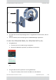
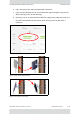
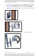
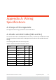
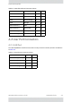
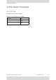
Table Of Contents
- Table of Contents
- Chapter 1: Introduction
- Chapter 2: Installation Steps
- 2.1 Prepare Laptop
- 2.2 Connect Laptop to Radio Unit
- 2.3 Update Connectivity Parameters of Radio Unit
- 2.4 Check items to be installed
- 2.5 Prepare Tools
- 2.6 Install Standard Mounting Kit
- 2.7 Install Mounting Kit for the SU PRO/AIR EMB
- 2.8 Mounting a Unit with the Standard Mounting Kit
- 2.9 Ground Radio Unit
- 2.10 Mounting the SU PRO/AIR EMB
- 2.11 Mounting the SU PRO/AIR INT
- 2.12 Mounting the Lightning Protection Units
- 2.13 Connect External Antenna (if applicable)
- 2.14 Waterproofing
- 2.15 Connect Radio (External Connections)
- 2.16 Check Connectivity to Radio
- 2.17 Activate Base Station
- 2.18 Align Subscriber Unit
- Chapter 3: Safety Practices and Provisions
- Appendix A: Wiring Specifications
- Appendix B: About Antennas
- Appendix C: Regional Notice: French Canadian
- Appendix A: Terminology
- Appendix E: Revision History
- Appendix F: Certified Antennas
- RADWIN Worldwide Offices

RADWIN5000InstallationGuideDQ0266610/A.01 A‐1
AppendixA:Wiring
Specifications
A.1ScopeofthisAppendix
ThisappendixshowswiringspecificationsfortheHBSandSU.
A.1Radiounit‐PoECable(HBSandSU)
Theradiounit‐PoEcableisshielded/outdoorclassCAT‐5e,4twisted‐pair24AWGterminated
withRJ‐45connectorsonbothends.Acableglandontheradiounitsideprovideshermetic
sealing.
Thefollowingtableshowstheconnectorpinout:
TableA‐1:Radiounit‐PoERJ‐45ConnectorPinout
Function Color PoE ODU
RxN
White/Green 1 1
RxT
Green 2 2
TxT
White/Orange 3 3
TxN
Orange 6 6
Power(+)
Blue 4 4
Power(+)
White/Blue 5 5
Power()
White/Brown 7 7
Power()
Brown 8 8