
Installation Guide
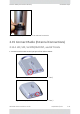

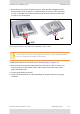
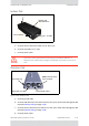
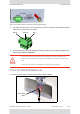
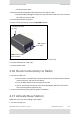
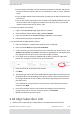
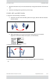
Table Of Contents
- Table of Contents
- Chapter 1: Introduction
- Chapter 2: Installation Steps
- 2.1 Prepare Laptop
- 2.2 Connect Laptop to Radio Unit
- 2.3 Update Connectivity Parameters of Radio Unit
- 2.4 Check items to be installed
- 2.5 Prepare Tools
- 2.6 Install Standard Mounting Kit
- 2.7 Install Mounting Kit for the SU PRO/AIR EMB
- 2.8 Mounting a Unit with the Standard Mounting Kit
- 2.9 Ground Radio Unit
- 2.10 Mounting the SU PRO/AIR EMB
- 2.11 Mounting the SU PRO/AIR INT
- 2.12 Mounting the Lightning Protection Units
- 2.13 Connect External Antenna (if applicable)
- 2.14 Waterproofing
- 2.15 Connect Radio (External Connections)
- 2.16 Check Connectivity to Radio
- 2.17 Activate Base Station
- 2.18 Align Subscriber Unit
- Chapter 3: Safety Practices and Provisions
- Appendix A: Wiring Specifications
- Appendix B: About Antennas
- Appendix C: Regional Notice: French Canadian
- Appendix A: Terminology
- Appendix E: Revision History
- Appendix F: Certified Antennas
- RADWIN Worldwide Offices

RADWIN5000InstallationGuide DQ0266610/A.01 2‐45
CheckConnectivitytoRadio InstallationSteps
2. RoutetheCAT‐5eandgroundcablesdownfromtheradiotoaPoE.
• Recommended,althoughnotrequired:routetheCAT‐5ecablevia2LPUs:onenear
theradio,onenearthePoE.
3. Connectgroundcabletoground.
4. PerformfinalconnectionsviatheSUPRO/AIREMBPoE:
5. ConnectCAT‐5ecablefromradioviathelowerLPUtothe“PoE”port.
6. ConnectLANcableto“LAN”port.
7. Connectpowercable.
2.16CheckConnectivitytoRadio
1. Connecttoradiounit:
• Fromalaptopinthefield:DisconnectthePoEfromthecommunicationsnetwork
(LANconnection),andconnectthelaptop.
• FromtheNOC:KeepthePoEconnectedtotheLAN.
• YoucanusetheSFPconnectionoftheJETDUO(labeled“LAN”)forcommunica‐
tionsandmanagementpurpose
sonly.
2. Fromacommandline,pingradiousingradio’sIPaddress.
2.17ActivateBaseStation
Applicableonlyifyouareinstallingabasestation.
1. Connecttoradiounit:
Connectionlabel:None
PoE:output
toradio
110‐220VACinput
(inrear)
LAN:Ethernetinput
fromnetwork