
Installation Guide

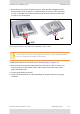
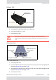
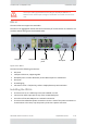
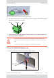
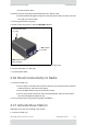
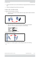
Table Of Contents
- Table of Contents
- Chapter 1: Introduction
- Chapter 2: Installation Steps
- 2.1 Prepare Laptop
- 2.2 Connect Laptop to Radio Unit
- 2.3 Update Connectivity Parameters of Radio Unit
- 2.4 Check items to be installed
- 2.5 Prepare Tools
- 2.6 Install Standard Mounting Kit
- 2.7 Install Mounting Kit for the SU PRO/AIR EMB
- 2.8 Mounting a Unit with the Standard Mounting Kit
- 2.9 Ground Radio Unit
- 2.10 Mounting the SU PRO/AIR EMB
- 2.11 Mounting the SU PRO/AIR INT
- 2.12 Mounting the Lightning Protection Units
- 2.13 Connect External Antenna (if applicable)
- 2.14 Waterproofing
- 2.15 Connect Radio (External Connections)
- 2.16 Check Connectivity to Radio
- 2.17 Activate Base Station
- 2.18 Align Subscriber Unit
- Chapter 3: Safety Practices and Provisions
- Appendix A: Wiring Specifications
- Appendix B: About Antennas
- Appendix C: Regional Notice: French Canadian
- Appendix A: Terminology
- Appendix E: Revision History
- Appendix F: Certified Antennas
- RADWIN Worldwide Offices

RADWIN5000InstallationGuide DQ0266610/A.01 2‐42
JETDUOandJETAIR/PROUnits InstallationSteps
IndoorPoE
Figure2‐49:IndoorPoEconnections
a. ConnectCAT‐5ecablefromlowerLPUto“Out”port
b. ConnectLANcableto“In”port.
c. Connectpowercable
OutdoorPoE
Connec tCAT‐ 5ecab lefromlo werLPUto“PoE”port,fastenwi thgland,addtape .
Figure2‐50:OutdoorPoE
a. Connectgroundcable.
b. ConnectLANcablefromthenetworktothe“ETH”port,fastenwithcablegland,add
tape(SeeWaterproofingonpage 2‐38).
c. ConnectCAT‐5ecablefromtheradiotothe“PoE”port,fastenwithcablegland,add
tape(SeeWaterproofingonpage 2‐38).
d. Connectpowercable.
UseonlyasafetyapprovedPoEaccordingtoIEC/EN/UL60950‐1or
62368‐1withratedoutputvoltageof24‐56VDCandratedcurrentof1A
max
110‐220VACinput(inrear)
Voltageand
dataindicators
In‐fromnetwork
Out‐toradio
110‐220VACinput
ETH:Ethernetinput
fromnetwork
PoE:outputtoradio
Groundinglug