
Installation Guide
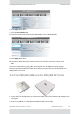
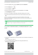
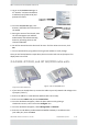
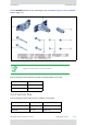
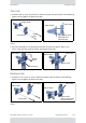
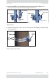
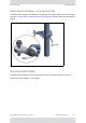
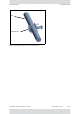
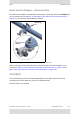
Table Of Contents
- Table of Contents
- Chapter 1: Introduction
- Chapter 2: Installation Steps
- 2.1 Prepare Laptop
- 2.2 Connect Laptop to Radio Unit
- 2.3 Update Connectivity Parameters of Radio Unit
- 2.4 Check items to be installed
- 2.5 Prepare Tools
- 2.6 Install Standard Mounting Kit
- 2.7 Install Mounting Kit for the SU PRO/AIR EMB
- 2.8 Mounting a Unit with the Standard Mounting Kit
- 2.9 Ground Radio Unit
- 2.10 Mounting the SU PRO/AIR EMB
- 2.11 Mounting the SU PRO/AIR INT
- 2.12 Mounting the Lightning Protection Units
- 2.13 Connect External Antenna (if applicable)
- 2.14 Waterproofing
- 2.15 Connect Radio (External Connections)
- 2.16 Check Connectivity to Radio
- 2.17 Activate Base Station
- 2.18 Align Subscriber Unit
- Chapter 3: Safety Practices and Provisions
- Appendix A: Wiring Specifications
- Appendix B: About Antennas
- Appendix C: Regional Notice: French Canadian
- Appendix A: Terminology
- Appendix E: Revision History
- Appendix F: Certified Antennas
- RADWIN Worldwide Offices

RADWIN5000InstallationGuide DQ0266610/A.01 2‐13
VerticalPole InstallationSteps
ThinPole
1. Diameter3/4”to11/2”(2cmto4cm):Positionthepoleclampasshowninthefollowing
figures.Donottightentheboltsallthewa y.
2. Placethisassemblyonthepolewhereyouwanttomountthedevice.Onceitisin
place,rotatethepoleclampasshown,thentightenbothbolts.
MediumPole
1. Diameter2”to3”(5cmto7.5cm):Positionthepoleclampasshowninthefollowing
figures.Donottightentheboltsallthewa y.
Figure2‐10:ConnectPoleClamptoRadio
Holder
Figure2‐11:Partiallytightenbolts
Figure2‐12:RotateClampandtighte nbolts Figure2‐13:Completelytightenbolts
Figure2‐14:ConnectPoleClamptoRadio
Holder
Figure2‐15:Tightenbolts
Radioholder
Poleclamp
Insert
bolts
Radioholder
Poleclamp
Tightenbolts,keep
spaceequalto
polediameter
Radioholder
Poleclamp
Rotate
clamp
Radioholder
Poleclamp
Tightenbolts
Radioholder
Poleclamp
Insertbolts
Radioholder
Poleclamp
Tightenbolts,
keepaspaceequal
topolediameter