
User's Manual
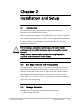


Chapter 2 Installation and Setup WinLink1000 Installation and Operation Manual
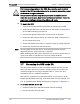
3. Connect the ODU cable to the RJ-45 connector on the IDU
designated ODU or WAN.
Figure
2-2
illustrates a typical IDU rear
panel.
Figure
2-3
illustrates a typical IDU-E front panel. There may
be differences in the panels of depending on the versions of the
IDU.
Æ
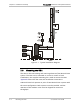
To connect the AIND to an external antenna
1. Connect one side of the coax cable to the N-type connector
marked ‘RF’ on the front of the AIND unit, and the other side to the
external antenna mounted on the pole.
TRUNK 1
LANODU
DC IN
48-60V --- 1A
+
-
TRUNK 2
Figure
2-2. Typical IDU Rear Panel
Figure
2-3. Typical IDU-C Front Panels
48VDC/1A
- GND +
Figure
2-4. WinLink1000-AIND All Indoor Radio Unit
Note
•
The IDU and IDU-C panels may be fitted with different connector
combinations depending on the model ordered.
2-6 Connecting the ODU to the IDU 9/18/2006 2:26:00 PM